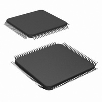
LM9830VJD/NOPB National Semiconductor, LM9830VJD/NOPB Datasheet - Page 11

LM9830VJD/NOPB
Manufacturer Part Number
LM9830VJD/NOPB
Description
IC SCANNER COLOR DOC 100-TQFP
Manufacturer
National Semiconductor
Datasheet
1.LM9830VJDNOPB.pdf
(45 pages)
Specifications of LM9830VJD/NOPB
Number Of Bits
12
Number Of Channels
3
Power (watts)
350mW
Voltage - Supply, Analog
5V
Voltage - Supply, Digital
4.5 V ~ 5.5 V
Package / Case
100-TQFP, 100-VQFP
Lead Free Status / RoHS Status
Lead free / RoHS Compliant
Other names
*LM9830VJD
*LM9830VJD/NOPB
LM9830VJD
*LM9830VJD/NOPB
LM9830VJD
Available stocks
Company
Part Number
Manufacturer
Quantity
Price
Company:
Part Number:
LM9830VJD/NOPB
Manufacturer:
Texas Instruments
Quantity:
10 000
Pin Descriptions
V
V
V
V
V
V
V
ø1
ø2
RS
CP1
CP2
TR1, TR2
OS
OS
CRYSTAL IN
CRYSTAL OUT Digital Output. Used with CRYSTAL IN and an
CLK_SEL
D0 (LSB) -D7
(MSB)
STROBE
AUTOFEED
SELECTIN
INIT
ACK
BUSY
PE
SELECT
ERROR
REF LO FORCE,
REF LO SENSE
REF MID FORCE,
REF MID SENSE
REF HI FORCE,
REF HI SENSE
BANDGAP
R
B
, OS
G
,
CCD Driver Signals
General Digital I/O
Digital Output. CCD/CIS clock signal, phase
1.
Digital Output. CCD clock signal, phase 2.
Digital Output. Reset pulse for the CCD.
Digital Output. Clamp pulse for the CCD.
Digital Output. Clamp pulse for the CCD.
Digital Outputs. Transfer pulses for the
CCD(CIS).
Analog Inputs. These inputs (for Red, Green,
and Blue) should be tied to the sensor’s out-
put signal through DC blocking capacitors.
Analog Output/Input. Connect V
V
monolithic capacitor.
Analog Output/Input. Connect V
to V
0.05µF monolithic capacitor.
Analog Output/Input. Connect V
V
monolithic capacitor.
Analog Output. Bypass to AGND with a
0.05µF monolithic capacitor.
Digital Input. This is the 50MHz (typical) mas-
ter system clock.
external crystal to form a crystal oscillator.
Digital Input. Should be tied to DGND for
operation with an external crystal. To use an
external TTL or CMOS clock source, tie
CLK_SEL to V
CRYSTAL OUT pin.
Digital Inputs/Outputs. This is the 8 bit data
path between the LM9830 and the host com-
puter.
Digital Input. WR signal in µP Mode.
Digital Input. RD signal in µP Mode.
Digital Input. ALE signal in µP Mode.
Digital Input. CS signal in µP Mode.
Digital Output.
Digital Output.
Digital Output.
Digital Output.
Digital Output.
REF LO IN
REF HI IN
REF MID IN
Analog I/O
PC I/O
and bypass to AGND with a 0.05µF
and bypass to AGND with a 0.05µF
D I/O
and bypass to AGND with a
and drive the clock into the
REF LO OUT
REF HI OUT
REF MID OUT
to
to
11
A, B, A, B
SENSE
SENSE
SENSE
LAMP
LAMP
TRISTATE
LATCH
PSense #1,
PSense #2
Misc I/O #1,
Misc I/O #2
DB0 (LSB) -
DB7 (MSB)
A0-A17
RD
WR
CMODE
TEST
V
AGND
A
R
G
,
, LAMP
A
B
GND
,
Analog Power Supplies
Communication Mode
Scanner Support I/O
B
Printer Passthrough
Stepper Motor I/O
External RAM I/O
Digital
passthrough mode, high when the LM9830 is
active. Low when no power is applied to the
LM9830.
Digital
passthrough mode, low when the LM9830 is
active. Tri-state when no power is applied to
the LM9830.
Digital Outputs. Pulses to stepper motor.
Analog Inputs. Current sensing for PWM
winding current control.
Analog Input. Ground sense input for PWM
winding current control.
Digital Inputs. Programmable, used for sens-
ing paper, front panel switches, etc.
Digital Inputs/Outputs. Programmable, used
for front panel switches, status LEDs, etc.
Digital Outputs. Used to control R, G, and B
LEDs of single output CIS, as well as bright-
ness of CCFL.
Digital Inputs/Outputs. This is the 8 bit data
path between the external RAM and the
LM9830.
Digital Outputs. Address pins for up to 256k
bytes external RAM.
Digital Output. Read signal to external RAM.
Digital Output. Write signal to external RAM.
Digital Input. Tie to DGND to operate in paral-
lel port mode, or to V
processor compatible mode.
Analog Output. This pin can be used to view
the Sample Signal, Sample Reference, and
Clamp Signals.
This is the positive supply pin for the analog
supply. It should be connected to a voltage
source of +5V and bypassed to AGND with a
0.1µF monolithic capacitor in parallel with a
10µF tantalum capacitor.
This is the ground return for the analog sup-
ply.
Output.
Output.
Test
High
Low
D I/O
http://www.national.com
to operate in micro-
when
when
in
in
printer
printer


