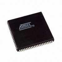
AT94K10AL-25AJI Atmel, AT94K10AL-25AJI Datasheet - Page 110

AT94K10AL-25AJI
Manufacturer Part Number
AT94K10AL-25AJI
Description
IC FPSLIC 10K GATE 25MHZ 84PLCC
Manufacturer
Atmel
Series
FPSLIC®r
Specifications of AT94K10AL-25AJI
Core Type
8-bit AVR
Speed
25MHz
Interface
I²C, UART
Program Sram Bytes
20K-32K
Fpga Sram
4kb
Data Sram Bytes
4K ~ 16K
Fpga Core Cells
576
Fpga Gates
10K
Fpga Registers
846
Voltage - Supply
3 V ~ 3.6 V
Mounting Type
Surface Mount
Operating Temperature
-40°C ~ 85°C
Package / Case
84-PLCC
For Use With
ATSTK594 - BOARD FPSLIC DAUGHTER FOR STK500
Lead Free Status / RoHS Status
Contains lead / RoHS non-compliant
Eeprom Size
-
Available stocks
Company
Part Number
Manufacturer
Quantity
Price
- Current page: 110 of 204
- Download datasheet (4Mb)
4.27
110
Watchdog Timer
AT94KAL Series FPSLIC
Table 4-22.
Notes:
In up/down PWM mode, the Timer Overflow Flag1, TOV1, is set when the counter advances
from $0000. In overflow PWM mode, the Timer Overflow flag is set as in normal Timer/Counter
mode. Timer Overflow Interrupt1 operates exactly as in normal Timer/Counter mode, i.e., it is
executed when TOV1 is set provided that Timer Overflow Interrupt1 and global interrupts are
enabled. This also applies to the Timer Output Compare1 flags and interrupts.
The Watchdog Timer is clocked from a separate on-chip oscillator which runs at 1 MHz. This is
the typical value at V
By controlling the Watchdog Timer prescaler, the watchdog reset interval can be adjusted, see
Table 4-23 on page 111
the Watchdog Timer. Eight different clock cycle periods can be selected to determine the reset
period. If the reset period expires without another watchdog reset, the FPSLIC resets and exe-
cutes from the reset vector.
To prevent unintentional disabling of the watchdog, a special turn-off sequence must be followed
when the watchdog is disabled, see
Figure 4-35. Watchdog Timer
COM1X1
1. In overflow PWM mode, this table is only valid for OCR1X = TOP.
2. X = A or B
1
1
1
1
(2)
PWM Outputs OCR1X = $0000 or TOP
CC
= 3.3V. See characterization data for typical values at other V
for a detailed description. The WDR (watchdog reset) instruction resets
COM1X0
0
0
1
1
(2)
Figure
4-35.
OCR1X
$0000
$0000
TOP
TOP
(1)
(2)
Output OC1X
H
H
L
L
1138I–FPSLI–1/08
(2)
CC
levels.
Related parts for AT94K10AL-25AJI
Image
Part Number
Description
Manufacturer
Datasheet
Request
R

Part Number:
Description:
Manufacturer:
Atmel
Datasheet:

Part Number:
Description:
IC FPSLIC 10K GATE 25MHZ 84PLCC
Manufacturer:
Atmel
Datasheet:

Part Number:
Description:
IC FPSLIC 10K GATE 25MHZ 100TQFP
Manufacturer:
Atmel
Datasheet:

Part Number:
Description:
IC FPSLIC 10K GATE 25MHZ 100TQFP
Manufacturer:
Atmel
Datasheet:

Part Number:
Description:
IC FPSLIC 10K GATE 25MHZ 144LQFP
Manufacturer:
Atmel
Datasheet:

Part Number:
Description:
IC FPSLIC 10K GATE 25MHZ 208PQFP
Manufacturer:
Atmel
Datasheet:

Part Number:
Description:
Manufacturer:
Atmel
Datasheet:

Part Number:
Description:
At94k05al 5k - 40k Gates Of At40k Fpga With 8-bit Microcontroller, Up To 36k Bytes Of Sram And On-chip Jtag Ice
Manufacturer:
ATMEL Corporation
Datasheet:

Part Number:
Description:
FPGA - Field Programmable Gate Array FPSLIC 10K GATE 8B 8B AVR 25MHZ TEMP
Manufacturer:
Atmel

Part Number:
Description:
FPGA - Field Programmable Gate Array ASICS
Manufacturer:
Atmel

Part Number:
Description:
FPGA - Field Programmable Gate Array FPSLIC 10K GATE 8B 8B AVR 25MHZ TEMP
Manufacturer:
Atmel

Part Number:
Description:
DEV KIT FOR AVR/AVR32
Manufacturer:
Atmel
Datasheet:

Part Number:
Description:
INTERVAL AND WIPE/WASH WIPER CONTROL IC WITH DELAY
Manufacturer:
ATMEL Corporation
Datasheet:

Part Number:
Description:
Low-Voltage Voice-Switched IC for Hands-Free Operation
Manufacturer:
ATMEL Corporation
Datasheet:


