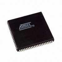
AT94K10AL-25AJI Atmel, AT94K10AL-25AJI Datasheet - Page 69

AT94K10AL-25AJI
Manufacturer Part Number
AT94K10AL-25AJI
Description
IC FPSLIC 10K GATE 25MHZ 84PLCC
Manufacturer
Atmel
Series
FPSLIC®r
Specifications of AT94K10AL-25AJI
Core Type
8-bit AVR
Speed
25MHz
Interface
I²C, UART
Program Sram Bytes
20K-32K
Fpga Sram
4kb
Data Sram Bytes
4K ~ 16K
Fpga Core Cells
576
Fpga Gates
10K
Fpga Registers
846
Voltage - Supply
3 V ~ 3.6 V
Mounting Type
Surface Mount
Operating Temperature
-40°C ~ 85°C
Package / Case
84-PLCC
For Use With
ATSTK594 - BOARD FPSLIC DAUGHTER FOR STK500
Lead Free Status / RoHS Status
Contains lead / RoHS non-compliant
Eeprom Size
-
Available stocks
Company
Part Number
Manufacturer
Quantity
Price
- Current page: 69 of 204
- Download datasheet (4Mb)
4.16.7
4.17
4.17.1
4.17.2
1138I–FPSLI–1/08
Sleep Modes
Interrupt Response Time
Idle Mode
Power-down Mode
The interrupt execution response for all the enabled AVR interrupts is four clock cycles mini-
mum. Four clock cycles after the interrupt flag has been set, the program vector address for the
actual interrupt handling routine is executed. During this four clock-cycle period, the Program
Counter (2 bytes) is pushed onto the Stack, and the Stack Pointer is decremented by 2. The
vector is normally a jump to the interrupt routine, and this jump takes three clock cycles. If an
interrupt occurs during execution of a multi-cycle instruction, this instruction is completed before
the interrupt is serviced.
A return from an interrupt handling routine (same as for a subroutine call routine) takes four
clock cycles. During these four clock cycles, the Program Counter (2 bytes) is popped back from
the Stack, and the Stack Pointer is incremented by 2. When the AVR exits from an interrupt, it
will always return to the main program and execute one more instruction before any pending
interrupt is serviced.
To enter any of the three Sleep modes, the SE bit in MCUR must be set (one) and a SLEEP
instruction must be executed. The SM1 and SM0 bits in the MCUR register select which Sleep
mode (Idle, Power-down, or Power-save) will be activated by the SLEEP instruction, see
4-3
In Power-down and Power-save modes, the four external interrupts, EXT_INT0...3, and FPGA
interrupts, FPGA INT0...3, are triggered as low level-triggered interrupts. If an enabled interrupt
occurs while the MCU is in a Sleep mode, the MCU awakes, executes the interrupt routine, and
resumes execution from the instruction following SLEEP. The contents of the register file,
SRAM, and I/O memory are unaltered. If a reset occurs during Sleep mode, the MCU wakes up
and executes from the Reset vector
When the SM1/SM0 bits are set to 00, the SLEEP instruction makes the MCU enter the Idle
mode, stopping the CPU but allowing UARTs, Timer/Counters, Watchdog 2-wire Serial and the
Interrupt System to continue operating. This enables the MCU to wake-up from external trig-
gered interrupts as well as internal ones like the Timer Overflow and UART Receive Complete
interrupts. When the MCU wakes up from Idle mode, the CPU starts program execution
immediately.
When the SM1/SM0 bits are set to 10, the SLEEP instruction makes the MCU enter the Power-
down mode. In this mode, the external oscillator is stopped, while the external interrupts and the
watchdog (if enabled) continue operating. Only an external reset, a watchdog reset (if enabled),
or an external level interrupt can wake-up the MCU.
In Power-down and Power-save modes, the four external interrupts, EXT_INT0...3, and FPGA
interrupts, FPGA_INT0...3, are treated as low-level triggered interrupts.
If a level-triggered interrupt is used for wake-up from Power-down mode, the changed level must
be held for some time to wake-up the MCU. This makes the MCU less sensitive to noise. The
changed level is sampled twice by the watchdog oscillator clock, and if the input has the required
level during this time, the MCU will wake-up. The period of the watchdog oscillator is 1 µs (nom-
inal) at 3.3V and 25° C. The frequency of the watchdog oscillator is voltage dependent.
on
page
54.
AT94KAL Series FPSLIC
Table
69
Related parts for AT94K10AL-25AJI
Image
Part Number
Description
Manufacturer
Datasheet
Request
R

Part Number:
Description:
Manufacturer:
Atmel
Datasheet:

Part Number:
Description:
IC FPSLIC 10K GATE 25MHZ 84PLCC
Manufacturer:
Atmel
Datasheet:

Part Number:
Description:
IC FPSLIC 10K GATE 25MHZ 100TQFP
Manufacturer:
Atmel
Datasheet:

Part Number:
Description:
IC FPSLIC 10K GATE 25MHZ 100TQFP
Manufacturer:
Atmel
Datasheet:

Part Number:
Description:
IC FPSLIC 10K GATE 25MHZ 144LQFP
Manufacturer:
Atmel
Datasheet:

Part Number:
Description:
IC FPSLIC 10K GATE 25MHZ 208PQFP
Manufacturer:
Atmel
Datasheet:

Part Number:
Description:
Manufacturer:
Atmel
Datasheet:

Part Number:
Description:
At94k05al 5k - 40k Gates Of At40k Fpga With 8-bit Microcontroller, Up To 36k Bytes Of Sram And On-chip Jtag Ice
Manufacturer:
ATMEL Corporation
Datasheet:

Part Number:
Description:
FPGA - Field Programmable Gate Array FPSLIC 10K GATE 8B 8B AVR 25MHZ TEMP
Manufacturer:
Atmel

Part Number:
Description:
FPGA - Field Programmable Gate Array ASICS
Manufacturer:
Atmel

Part Number:
Description:
FPGA - Field Programmable Gate Array FPSLIC 10K GATE 8B 8B AVR 25MHZ TEMP
Manufacturer:
Atmel

Part Number:
Description:
DEV KIT FOR AVR/AVR32
Manufacturer:
Atmel
Datasheet:

Part Number:
Description:
INTERVAL AND WIPE/WASH WIPER CONTROL IC WITH DELAY
Manufacturer:
ATMEL Corporation
Datasheet:

Part Number:
Description:
Low-Voltage Voice-Switched IC for Hands-Free Operation
Manufacturer:
ATMEL Corporation
Datasheet:


