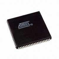
AT94K10AL-25AJI Atmel, AT94K10AL-25AJI Datasheet - Page 158

AT94K10AL-25AJI
Manufacturer Part Number
AT94K10AL-25AJI
Description
IC FPSLIC 10K GATE 25MHZ 84PLCC
Manufacturer
Atmel
Series
FPSLIC®r
Specifications of AT94K10AL-25AJI
Core Type
8-bit AVR
Speed
25MHz
Interface
I²C, UART
Program Sram Bytes
20K-32K
Fpga Sram
4kb
Data Sram Bytes
4K ~ 16K
Fpga Core Cells
576
Fpga Gates
10K
Fpga Registers
846
Voltage - Supply
3 V ~ 3.6 V
Mounting Type
Surface Mount
Operating Temperature
-40°C ~ 85°C
Package / Case
84-PLCC
For Use With
ATSTK594 - BOARD FPSLIC DAUGHTER FOR STK500
Lead Free Status / RoHS Status
Contains lead / RoHS non-compliant
Eeprom Size
-
Available stocks
Company
Part Number
Manufacturer
Quantity
Price
- Current page: 158 of 204
- Download datasheet (4Mb)
4.31
4.31.1
4.31.1.1
158
I/O Ports
AT94KAL Series FPSLIC
PortD
PortD as General Digital I/O
All AVR ports have true read-modify-write functionality when used as general I/O ports. This
means that the direction of one port pin can be changed without unintentionally changing the
direction of any other pin with the SBI and CBI instructions. The same applies for changing drive
value (if configured as output) or enabling/disabling of pull-up resistors (if configured as input).
PortD is an 8-bit bi-directional I/O port with internal pull-up resistors.
Three I/O memory address locations are allocated for the PortD, one each for the Data Register
– PORTD, $12($32), Data Direction Register – DDRD, $11($31) and the Port D Input Pins –
PIND, $10($30). The Port D Input Pins address is read only, while the Data Register and the
Data Direction Register are read/write.
The PortD output buffers can sink 20 mA. As inputs, PortD pins that are externally pulled Low
will source current if the pull-up resistors are activated.
PortD Data Register – PORTD
PortD Data Direction Register – DDRD
PortD Input Pins Address – PIND
The PortD Input Pins address – PIND – is not a register, and this address enables access to the
physical value on each PortD pin. When reading PORTD, the PortD Data Latch is read, and
when reading PIND, the logical values present on the pins are read.
PDn, General I/O pin: The DDDn bit in the DDRD register selects the direction of this pin. If
DDDn is set (one), PDn is configured as an output pin. If DDDn is cleared (zero), PDn is config-
ured as an input pin. If PDn is set (one) when configured as an input pin the MOS pull-up resistor
is activated. To switch the pull-up resistor off the PDn has to be cleared (zero) or the pin has to
be configured as an output pin. The port pins are input with pull-up when a reset condition
becomes active, even if the clock is not running, see
Bit
$12
Read/Write
Initial Value
Bit
$11
Read/Write
Initial Value
Bit
$10
Read/Write
Initial Value
7
PORTD7
R/W
1
7
DDD7
R/W
0
7
PIND7
R
Pull1
6
PORTD6
R/W
1
6
DDD6
R/W
0
6
PIND6
R
Pull1
5
PORTD5
R/W
1
5
PIND5
R
Pull1
5
DDD5
R/W
0
4
PORTD4
R/W
1
Pull1
4
DDD4
R/W
0
4
PIND4
R
3
DDD3
R/W
0
3
PIND3
R
Pull1
3
PORTD3
R/W
1
Table
4-34.
2
PIND2
R
Pull1
2
DDD2
R/W
0
2
PORTD2
R/W
1
1
PIND1
R
Pull1
1
DDD1
R/W
0
1
PORTD1
R/W
1
Pull1
0
DDD0
R/W
0
0
PIND0
R
0
PORTD0
R/W
1
1138I–FPSLI–1/08
PIND
DDRD
PORTD
Related parts for AT94K10AL-25AJI
Image
Part Number
Description
Manufacturer
Datasheet
Request
R

Part Number:
Description:
Manufacturer:
Atmel
Datasheet:

Part Number:
Description:
IC FPSLIC 10K GATE 25MHZ 84PLCC
Manufacturer:
Atmel
Datasheet:

Part Number:
Description:
IC FPSLIC 10K GATE 25MHZ 100TQFP
Manufacturer:
Atmel
Datasheet:

Part Number:
Description:
IC FPSLIC 10K GATE 25MHZ 100TQFP
Manufacturer:
Atmel
Datasheet:

Part Number:
Description:
IC FPSLIC 10K GATE 25MHZ 144LQFP
Manufacturer:
Atmel
Datasheet:

Part Number:
Description:
IC FPSLIC 10K GATE 25MHZ 208PQFP
Manufacturer:
Atmel
Datasheet:

Part Number:
Description:
Manufacturer:
Atmel
Datasheet:

Part Number:
Description:
At94k05al 5k - 40k Gates Of At40k Fpga With 8-bit Microcontroller, Up To 36k Bytes Of Sram And On-chip Jtag Ice
Manufacturer:
ATMEL Corporation
Datasheet:

Part Number:
Description:
FPGA - Field Programmable Gate Array FPSLIC 10K GATE 8B 8B AVR 25MHZ TEMP
Manufacturer:
Atmel

Part Number:
Description:
FPGA - Field Programmable Gate Array ASICS
Manufacturer:
Atmel

Part Number:
Description:
FPGA - Field Programmable Gate Array FPSLIC 10K GATE 8B 8B AVR 25MHZ TEMP
Manufacturer:
Atmel

Part Number:
Description:
DEV KIT FOR AVR/AVR32
Manufacturer:
Atmel
Datasheet:

Part Number:
Description:
INTERVAL AND WIPE/WASH WIPER CONTROL IC WITH DELAY
Manufacturer:
ATMEL Corporation
Datasheet:

Part Number:
Description:
Low-Voltage Voice-Switched IC for Hands-Free Operation
Manufacturer:
ATMEL Corporation
Datasheet:


