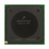
MPC8379EVRAJF Freescale Semiconductor, MPC8379EVRAJF Datasheet - Page 108

MPC8379EVRAJF
Manufacturer Part Number
MPC8379EVRAJF
Description
MPU PWRQUICC II 533MHZ 689TEPBGA
Manufacturer
Freescale Semiconductor
Series
PowerQUICC II PROr
Datasheets
1.MPC8377EVRAGD.pdf
(126 pages)
2.MPC8377EVRAGD.pdf
(2 pages)
3.MPC8379VRAGD.pdf
(116 pages)
Specifications of MPC8379EVRAJF
Processor Type
MPC83xx PowerQUICC II Pro 32-Bit
Speed
533MHz
Voltage
1V
Mounting Type
Surface Mount
Package / Case
689-TePBGA II
Maximum Clock Frequency
533 MHz
Operating Supply Voltage
1.8 V to 2.5 V
Maximum Operating Temperature
+ 105 C
Mounting Style
SMD/SMT
I/o Voltage
1.8 V, 2.5 V, 3.3 V
Minimum Operating Temperature
0 C
Core Size
32 Bit
Program Memory Size
64KB
Cpu Speed
533MHz
Embedded Interface Type
DUART, HSSI, I2C, IPIC, JTAG, SPI, USB
Digital Ic Case Style
BGA
No. Of Pins
689
Rohs Compliant
Yes
For Use With
MPC8377E-RDBA - BOARD REF DES MPC8377 REV 2.1MPC8377E-MDS-PB - BOARD MODULAR DEV SYSTEM
Lead Free Status / RoHS Status
Lead free / RoHS Compliant
Features
-
Lead Free Status / Rohs Status
Lead free / RoHS Compliant
Available stocks
Company
Part Number
Manufacturer
Quantity
Price
Company:
Part Number:
MPC8379EVRAJF
Manufacturer:
Freescale Semiconductor
Quantity:
135
Company:
Part Number:
MPC8379EVRAJF
Manufacturer:
Freescale Semiconductor
Quantity:
10 000
Thermal
Interface material vendors include the following:
23.3
The device requires the use of heat sinks. When heat sinks are attached, an interface material is required,
preferably thermal grease and a spring clip. The spring clip should connect to the printed circuit board,
either to the board itself, to hooks soldered to the board, or to a plastic stiffener. Avoid attachment forces
that can lift the edge of the package or peel the package from the board. Such peeling forces reduce the
solder joint lifetime of the package. The recommended maximum compressive force on the top of the
package is 10 lb force (4.5 kg force). Any adhesive attachment should attach to painted or plastic surfaces,
and its performance should be verified under the application requirements.
23.3.1
When a heat sink is used, the junction temperature is determined from a thermocouple inserted at the
interface between the case of the package and the interface material. A clearance slot or hole is normally
required in the heat sink. Minimize the size of the clearance to minimize the change in thermal
performance caused by removing part of the thermal interface to the heat sink. Because of the experimental
difficulties with this technique, many engineers measure the heat sink temperature and then back calculate
the case temperature using a separate measurement of the thermal resistance of the interface. From this
case temperature, the junction temperature is determined from the junction to case thermal resistance.
108
Tyco Electronics
Chip Coolers™
www.chipcoolers.com
Wakefield Engineering
www.wakefield.com
Chomerics, Inc.
www.chomerics.com
Dow-Corning Corporation
Dow-Corning Electronic Materials
www.dowcorning.com
Shin-Etsu MicroSi, Inc.
www.microsi.com
The Bergquist Company
www.bergquistcompany.com
Heat Sink Attachment
Experimental Determination of the Junction Temperature with a
Heat Sink
T
where:
MPC8379E PowerQUICC II Pro Processor Hardware Specifications, Rev. 4
J
= T
T
T
C
J
C
+ (R
= junction temperature (°C)
= case temperature of the package (°C)
θ
JC
× P
D
)
Freescale Semiconductor


