XPC8240LZU200E Freescale Semiconductor, XPC8240LZU200E Datasheet - Page 33
XPC8240LZU200E
Manufacturer Part Number
XPC8240LZU200E
Description
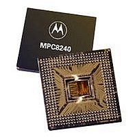
MCU HOST PROCESSOR 352-TBGA
Manufacturer
Freescale Semiconductor
Series
PowerQUICC IIr
Specifications of XPC8240LZU200E
Processor Type
MPC82xx PowerQUICC II 32-bit
Speed
200MHz
Voltage
2.5V
Mounting Type
Surface Mount
Package / Case
352-TBGA
Core Size
32 Bit
Program Memory Size
32KB
Cpu Speed
200MHz
Embedded Interface Type
I2C
Digital Ic Case Style
TBGA
No. Of Pins
352
Supply Voltage Range
2.5V To 2.75V
Rohs Compliant
No
Lead Free Status / RoHS Status
Contains lead / RoHS non-compliant
Features
-
Available stocks
Company
Part Number
Manufacturer
Quantity
Price
Company:

Part Number:
XPC8240LZU200E
Manufacturer:
MOTOLOLA
Quantity:
319
Company:
Part Number:
XPC8240LZU200E
Manufacturer:
Freescale Semiconductor
Quantity:
10 000
Part Number:
XPC8240LZU200E
Manufacturer:
FREESCALE
Quantity:
20 000


MPC8240 Integrated Processor Hardware Specifications
AV
DA2
DA[11:13]
DA[14:15]
Notes:
1. Place pull-up resistors of 120 Ω or less on the TEST0 pin.
2. Treat these pins as no connects unless using debug address functionality.
3. This pin has an internal pull-up resistor that is enabled only when the MPC8240 is in the reset state. The value of
4. This pin is a reset configuration pin.
5. DL[0] is a reset configuration pin and has an internal pull-up resistor that is enabled only when the MPC8240 is in
6. Multi-pin signals such as AD[0:31] or DL[0:31] have their physical package pin numbers listed in order
7. GNT4 is a reset configuration pin and has an internal pull-up resistor that is enabled only when the MPC8240 is in
8. Recommend a weak pull-up resistor (2–10 kΩ) be placed on this PCI control pin to LV
9. V
10.Recommend a weak pull-up resistor (2–10 kΩ) be placed on this pin to OV
11.Recommend a weak pull-up resistor (2–10 kΩ) be placed on this pin to GV
12.This pin has an internal pull-up resistor; the value of the internal pull-up resistor is not guaranteed, but is sufficient
13.Output valid specifications for this pin are memory interface mode dependent (registered or flow-through), see
14.Non-DRAM access output valid specification applies to this pin during non-DRAM accesses, see specification 12b3
15.This pin is affected by programmable PCI_HOLD_DEL parameter, see Section 1.4.2.4.1, “PCI Signal Output Hold
16.This pin is an open drain signal.
17.This pin can be programmed to be driven (default) or can be programmed to be open drain; see the PMCR2 register
18.This pin is a sustained three-state pin as defined by the PCI Local Bus Specification.
19.Maximum input voltage tolerance is LV
DD
the internal pull-up resistor is not guaranteed but is sufficient to ensure that a 1 is read into configuration bits during
reset.
the reset state.The value of the internal pull-up resistor is not guaranteed, but is sufficient to ensure that a one is
read into configuration bits during reset.
corresponding to the signal names. Example: AD0 is on pin C22, AD1 is on pin D22,...AD31 is on pin V25.
the reset state.The value of the internal pull-up resistor is not guaranteed but is sufficient to ensure that a one is
read into configuration bits during reset.
to prevent unused inputs from floating.
Table 9.
in Table 9.
Timing.”
description in the MPC8240 Integrated Processor User’s Manual, for details.
IH
2
and V
Name
IL
for these signals are the same as the PCI V
AF24
C25
AD26 AF17 AF19
F1 J2
Freescale Semiconductor, Inc.
Table 17. MPC8240 Pinout Listing (continued)
For More Information On This Product,
Pin Number
DD
Go to: www.freescale.com
-based. See Table 2 for details.
Manufacturing Pins
IH
logic) 2.5 V
and V
(peripheral
Power for
Pin Type
Output
Output
Output
PLL
IL
entries in Table 3.
Supply
Power
AV
DD
DD
OV
OV
GV
.
DD
.
DD
DD
DD
2
DD
DRV_MEM_
DRV_PCI
DRV_PCI
.
Output
Driver
ADDR
Package Description
Type
—
Notes
2, 6
2, 6
2
33
Related parts for XPC8240LZU200E
Image
Part Number
Description
Manufacturer
Datasheet
Request
R

Part Number:
Description:
Manufacturer:
Freescale Semiconductor, Inc
Datasheet:
Part Number:
Description:
Manufacturer:
Freescale Semiconductor, Inc
Datasheet:
Part Number:
Description:
Manufacturer:
Freescale Semiconductor, Inc
Datasheet:
Part Number:
Description:
Manufacturer:
Freescale Semiconductor, Inc
Datasheet:
Part Number:
Description:
Manufacturer:
Freescale Semiconductor, Inc
Datasheet:
Part Number:
Description:
Manufacturer:
Freescale Semiconductor, Inc
Datasheet:
Part Number:
Description:
Manufacturer:
Freescale Semiconductor, Inc
Datasheet:
Part Number:
Description:
Manufacturer:
Freescale Semiconductor, Inc
Datasheet:
Part Number:
Description:
Manufacturer:
Freescale Semiconductor, Inc
Datasheet:
Part Number:
Description:
Manufacturer:
Freescale Semiconductor, Inc
Datasheet:
Part Number:
Description:
Manufacturer:
Freescale Semiconductor, Inc
Datasheet:
Part Number:
Description:
Manufacturer:
Freescale Semiconductor, Inc
Datasheet:
Part Number:
Description:
Manufacturer:
Freescale Semiconductor, Inc
Datasheet:
Part Number:
Description:
Manufacturer:
Freescale Semiconductor, Inc
Datasheet:
Part Number:
Description:
Manufacturer:
Freescale Semiconductor, Inc
Datasheet: