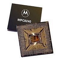
XPC8240LZU200E Freescale Semiconductor, XPC8240LZU200E Datasheet - Page 39

XPC8240LZU200E
Manufacturer Part Number
XPC8240LZU200E
Description
MCU HOST PROCESSOR 352-TBGA
Manufacturer
Freescale Semiconductor
Series
PowerQUICC IIr
Specifications of XPC8240LZU200E
Processor Type
MPC82xx PowerQUICC II 32-bit
Speed
200MHz
Voltage
2.5V
Mounting Type
Surface Mount
Package / Case
352-TBGA
Core Size
32 Bit
Program Memory Size
32KB
Cpu Speed
200MHz
Embedded Interface Type
I2C
Digital Ic Case Style
TBGA
No. Of Pins
352
Supply Voltage Range
2.5V To 2.75V
Rohs Compliant
No
Lead Free Status / RoHS Status
Contains lead / RoHS non-compliant
Features
-
Available stocks
Company
Part Number
Manufacturer
Quantity
Price
Company:
Part Number:
XPC8240LZU200E
Manufacturer:
MOTOLOLA
Quantity:
319
Company:
Part Number:
XPC8240LZU200E
Manufacturer:
Freescale Semiconductor
Quantity:
10 000
Part Number:
XPC8240LZU200E
Manufacturer:
FREESCALE
Quantity:
20 000
1.7.7
The MPC8240 PCI reference voltage (LV
interfacing the MPC8240 into a 3.3-V PCI bus system. Similarly, the LV
5.0 ±5% V power supply if interfacing the MPC8240 into a 5-V PCI bus system. For either reference
MPC8240 Integrated Processor Hardware Specifications
Notes:
Physical Pin Out
COP Connector
1. QACK is an output on the MPC8240 and is not required at the COP header for emulation.
2. RUN/STOP normally found on pin 5 of the COP header is not implemented on the MPC8240.
3. CKSTP_OUT normally found on pin 15 of the COP header is not implemented on the MPC8240.
4. Pin 14 is not physically present on the COP header.
5. SRESET functions as output SDMA12 in extended ROM mode.
6. CHKSTOP_IN functions as output SDMA14 in extended ROM mode.
Connect pin 5 of the COP header to OV
Connect pin 15 of the COP header to OV
PCI Reference Voltage—LV
13
15
11
1
1
3
5
7
9
No pin
KEY
Board Sources
10
12
16
2
4
6
8
From Target
(if any)
Freescale Semiconductor, Inc.
Key
For More Information On This Product,
SRESET
15
14
HRESET
5
13
11
12
Figure 25. COP Connector Diagram
10
16
4
6
2
2
3
4
8
1
3
7
9
VDD_SENSE
TDO
SRESET
TMS
TDI
TCK
HRESET
TRST
CHKSTOP_IN
Go to: www.freescale.com
5
NC
NC
NC
DD
) pins should be connected to 3.3 ±0.3 V power supply if
5
DD
DD
with a 1-kΩ pull-up resistor.
6
with a 10-kΩ pull-up resistor.
DD
10 kΩ
1 kΩ
10 kΩ
10 kΩ
10 kΩ
10 kΩ
10 kΩ
10 kΩ
DD
System Design Information
pins should be connected to
TDO
OV
OV
OV
OV
OV
OV
TMS
TCK
HRST_CTRL
OV
CHKSTOP_IN
TDI
HRST_CPU
OV
TRST
QACK
SRESET
DD
DD
DD
DD
MPC8240
DD
DD
DD
DD
1
5
6
39


