XPC8240LZU200E Freescale Semiconductor, XPC8240LZU200E Datasheet - Page 35
XPC8240LZU200E
Manufacturer Part Number
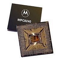
XPC8240LZU200E
Description
MCU HOST PROCESSOR 352-TBGA
Manufacturer
Freescale Semiconductor
Series
PowerQUICC IIr
Specifications of XPC8240LZU200E
Processor Type
MPC82xx PowerQUICC II 32-bit
Speed
200MHz
Voltage
2.5V
Mounting Type
Surface Mount
Package / Case
352-TBGA
Core Size
32 Bit
Program Memory Size
32KB
Cpu Speed
200MHz
Embedded Interface Type
I2C
Digital Ic Case Style
TBGA
No. Of Pins
352
Supply Voltage Range
2.5V To 2.75V
Rohs Compliant
No
Lead Free Status / RoHS Status
Contains lead / RoHS non-compliant
Features
-
Available stocks
Company
Part Number
Manufacturer
Quantity
Price
Company:

Part Number:
XPC8240LZU200E
Manufacturer:
MOTOLOLA
Quantity:
319
Company:
Part Number:
XPC8240LZU200E
Manufacturer:
Freescale Semiconductor
Quantity:
10 000
Part Number:
XPC8240LZU200E
Manufacturer:
FREESCALE
Quantity:
20 000


1.7
This section provides electrical and thermal design recommendations for successful application of the
MPC8240.
1.7.1
The AV
logic/memory bus PLL, MPC603e processor PLL, and SDRAM clock delay-locked loop (DLL),
respectively. To ensure stability of the internal clocks, the power supplied to the AV
input signals should be filtered of any noise in the 500-KHz to 10-MHz resonant frequency range of the
PLLs. Three separate circuits similar to the one shown in Figure 24 using surface mount capacitors with
minimum effective series inductance (ESL) is recommended for AV
pins. Consistent with the recommendations of Dr. Howard Johnson in High Speed Digital Design: A
Handbook of Black Magic (Prentice Hall, 1993), using multiple small capacitors of equal value is
recommended over using multiple values.
The circuits should be placed as close as possible to the respective input signal pins to minimize noise
coupled from nearby circuits. Routing directly as possible from the capacitors to the input signal pins with
minimal inductance of vias is important.
MPC8240 Integrated Processor Hardware Specifications
Notes:
1. The processor HID1 values only represent the multiplier of the processor’s PLL (memory-to-processor multiplier);
2. PLL_CFG[0:4] settings not listed (00110, 01001, 01011, 01101, 01111, 10001, 10011, 10101, 10111, 11001, and
3. In PLL-bypass mode, the PCI_SYNC_IN input signal clocks the internal processor directly, the peripheral logic PLL
4. In clock-off mode, no clocking occurs inside the MPC8240 regardless of the PCI_SYNC_IN input.
5. Limited due to maximum memory VCO = 225 MHz.
6. Limited due to minimum CPU VCO = 200 MHz.
7. Limited due to minimum memory VCO = 100 MHz.
8. For clarity, range values are shown rounded down to the nearest whole number (decimal place accuracy removed).
9. Note that the 250-MHz part is available only in the XPC8240RZUnnnx number series.
Ref.
No.
1E
1F
thus, multiple MPC8240 PLL_CFG[0:4] values may have the same processor HID1 value. This implies that system
software cannot read the HID1 register and associate it with a unique PLL_CFG[0:4] value.
11011) are reserved.
is disabled, and the bus mode is set for 1:1 (PCI:Mem) mode operation. This mode is intended for hardware
modeling support. The AC timing specifications given in this document do not apply in the PLL-bypass mode.
PLL_CFG
DD
[0:4]
11110
11111
System Design Information
, AV
PLL Power Supply Filtering
2
DD
Table 18. MPC8240 Microprocessor PLL Configurations (continued)
2, and LAV
CPU
01111
11111
[0:4]
1
HID1
Freescale Semiconductor, Inc.
For More Information On This Product,
DD
PCI Clock Input
(PCI_SYNC_IN)
Range (MHz)
power signals on the MPC8240 provide power to the peripheral
Go to: www.freescale.com
200 MHz Part
Logic/ Mem Bus
Not usable
Clock Range
Peripheral
(MHz)
8,9
CPU Clock
Range
DD
(MHz)
, AV
DD
System Design Information
2, and LAV
PCI-to-Mem
(Mem VCO)
Multiplier
DD
Off
Off
, AV
Ratios
DD
DD
2, and LAV
Mem-to-CPU
power signal
(CPU VCO)
Multiplier
3,4
Off
Off
35
DD
Related parts for XPC8240LZU200E
Image
Part Number
Description
Manufacturer
Datasheet
Request
R

Part Number:
Description:
Manufacturer:
Freescale Semiconductor, Inc
Datasheet:
Part Number:
Description:
Manufacturer:
Freescale Semiconductor, Inc
Datasheet:
Part Number:
Description:
Manufacturer:
Freescale Semiconductor, Inc
Datasheet:
Part Number:
Description:
Manufacturer:
Freescale Semiconductor, Inc
Datasheet:
Part Number:
Description:
Manufacturer:
Freescale Semiconductor, Inc
Datasheet:
Part Number:
Description:
Manufacturer:
Freescale Semiconductor, Inc
Datasheet:
Part Number:
Description:
Manufacturer:
Freescale Semiconductor, Inc
Datasheet:
Part Number:
Description:
Manufacturer:
Freescale Semiconductor, Inc
Datasheet:
Part Number:
Description:
Manufacturer:
Freescale Semiconductor, Inc
Datasheet:
Part Number:
Description:
Manufacturer:
Freescale Semiconductor, Inc
Datasheet:
Part Number:
Description:
Manufacturer:
Freescale Semiconductor, Inc
Datasheet:
Part Number:
Description:
Manufacturer:
Freescale Semiconductor, Inc
Datasheet:
Part Number:
Description:
Manufacturer:
Freescale Semiconductor, Inc
Datasheet:
Part Number:
Description:
Manufacturer:
Freescale Semiconductor, Inc
Datasheet:
Part Number:
Description:
Manufacturer:
Freescale Semiconductor, Inc
Datasheet: