MPC8544VTALF Freescale Semiconductor, MPC8544VTALF Datasheet - Page 28
MPC8544VTALF
Manufacturer Part Number
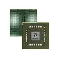
MPC8544VTALF
Description
MPU POWERQUICC III 783-PBGA
Manufacturer
Freescale Semiconductor
Datasheets
1.MPC8544VTALF.pdf
(117 pages)
2.MPC8544VTALF.pdf
(2 pages)
3.MPC8544VTALF.pdf
(1340 pages)
Specifications of MPC8544VTALF
Processor Type
MPC85xx PowerQUICC III 32-Bit
Speed
667MHz
Voltage
1V
Mounting Type
Surface Mount
Package / Case
783-FCPBGA
Processor Series
MPC85xx
Core
e500
Data Bus Width
32 bit
Maximum Clock Frequency
667 MHz
Maximum Operating Temperature
+ 105 C
Mounting Style
SMD/SMT
Data Ram Size
32 KB
I/o Voltage
1.8 V, 3.3 V
Interface Type
I2C, HSSI, DUART
Minimum Operating Temperature
0 C
Lead Free Status / RoHS Status
Lead free / RoHS Compliant
Features
-
Lead Free Status / Rohs Status
Lead free / RoHS Compliant
Available stocks
Company
Part Number
Manufacturer
Quantity
Price
Company:

Part Number:
MPC8544VTALF
Manufacturer:
Freescale Semiconductor
Quantity:
10 000
Company:
Part Number:
MPC8544VTALFA
Manufacturer:
Freescale Semiconductor
Quantity:
10 000


Enhanced Three-Speed Ethernet (eTSEC), MII Management
8.4
This section describes the SGMII transmit and receive AC timing specifications. Transmitter and receiver
characteristics are measured at the transmitter outputs (SD2_TX[n] and SD2_TX[n]) or at the receiver
inputs (SD2_RX[n] and SD2_RX[n]) as depicted in
8.4.1
Table 26
28
At recommended operating conditions with XVDD_SRDS2 = 1.0 V ± 5%.
Input differential voltage
Loss of signal threshold
Input AC common mode voltage
Receiver differential input impedance
Receiver common mode input impedance
Common mode input voltage
Notes:
1. Input must be externally AC-coupled.
2. V
3. The concept of this parameter is equivalent to the electrical idle detect threshold parameter in PCI Express. Refer to
4. The LSTS shown in this table refers to the LSTSCD bit field of MPC8544E SerDes 2 control register 1.
5. V
6. On-chip termination to SGND_SRDS2 (xcorevss).
Deterministic jitter
Total jitter
Unit interval
V
V
Notes;
1. Source synchronous clock is not supported.
2. Each UI value is 800 ps ± 100 ppm.
OD
OD
Section 17.4.3, “Differential Receiver (RX) Input Specifications,”
RX_DIFFp-p
CM_ACp-p
fall time (80%–20%)
rise time (20%–80%)
provides the SGMII transmit AC timing targets. A source synchronous clock is not provided.
SGMII AC Timing Specifications
is also referred to as peak-to-peak AC common mode voltage.
SGMII Transmit AC Timing Specifications
is also referred to as peak-to-peak input differential voltage
Parameter
MPC8544E PowerQUICC III Integrated Processor Hardware Specifications, Rev. 5
Parameter
Table 25. DC Receiver Electrical Characteristics (continued)
Table 26. SGMII Transmit AC Timing Specifications
LSTS = 0
LSTS = 1
LSTS = 0
LSTS = 1
Symbol
t
t
J
rise
J
U
fall
D
T
I
V
V
Symbol
Zrx_diff
Zrx_cm
cm_acpp
rx_diffpp
Vcm
Vl
os
Figure
799.92
Min
for further explanation.
50
50
—
—
xcorevss
Min
100
175
10, respectively.
30
65
80
20
—
Typ
800
—
—
—
—
Typ
—
—
—
—
—
—
—
—
xcorevss
800.08
Max
0.17
0.35
120
120
1200
Max
100
175
100
120
35
Freescale Semiconductor
UI p-p
UI p-p
Unit
Unit
mV
mV
mV
ps
ps
ps
Ω
Ω
V
Notes
Notes
2, 4
3, 4
—
—
—
—
—
—
5.
6
2
Related parts for MPC8544VTALF
Image
Part Number
Description
Manufacturer
Datasheet
Request
R

Part Number:
Description:
Manufacturer:
Freescale Semiconductor, Inc
Datasheet:
Part Number:
Description:
Manufacturer:
Freescale Semiconductor, Inc
Datasheet:
Part Number:
Description:
Manufacturer:
Freescale Semiconductor, Inc
Datasheet:
Part Number:
Description:
Manufacturer:
Freescale Semiconductor, Inc
Datasheet:
Part Number:
Description:
Manufacturer:
Freescale Semiconductor, Inc
Datasheet:
Part Number:
Description:
Manufacturer:
Freescale Semiconductor, Inc
Datasheet:
Part Number:
Description:
Manufacturer:
Freescale Semiconductor, Inc
Datasheet:
Part Number:
Description:
Manufacturer:
Freescale Semiconductor, Inc
Datasheet:
Part Number:
Description:
Manufacturer:
Freescale Semiconductor, Inc
Datasheet:
Part Number:
Description:
Manufacturer:
Freescale Semiconductor, Inc
Datasheet:
Part Number:
Description:
Manufacturer:
Freescale Semiconductor, Inc
Datasheet:
Part Number:
Description:
Manufacturer:
Freescale Semiconductor, Inc
Datasheet:
Part Number:
Description:
Manufacturer:
Freescale Semiconductor, Inc
Datasheet:
Part Number:
Description:
Manufacturer:
Freescale Semiconductor, Inc
Datasheet:
Part Number:
Description:
Manufacturer:
Freescale Semiconductor, Inc
Datasheet: