MPC8544VTALF Freescale Semiconductor, MPC8544VTALF Datasheet - Page 75
MPC8544VTALF
Manufacturer Part Number
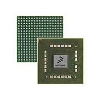
MPC8544VTALF
Description
MPU POWERQUICC III 783-PBGA
Manufacturer
Freescale Semiconductor
Datasheets
1.MPC8544VTALF.pdf
(117 pages)
2.MPC8544VTALF.pdf
(2 pages)
3.MPC8544VTALF.pdf
(1340 pages)
Specifications of MPC8544VTALF
Processor Type
MPC85xx PowerQUICC III 32-Bit
Speed
667MHz
Voltage
1V
Mounting Type
Surface Mount
Package / Case
783-FCPBGA
Processor Series
MPC85xx
Core
e500
Data Bus Width
32 bit
Maximum Clock Frequency
667 MHz
Maximum Operating Temperature
+ 105 C
Mounting Style
SMD/SMT
Data Ram Size
32 KB
I/o Voltage
1.8 V, 3.3 V
Interface Type
I2C, HSSI, DUART
Minimum Operating Temperature
0 C
Lead Free Status / RoHS Status
Lead free / RoHS Compliant
Features
-
Lead Free Status / Rohs Status
Lead free / RoHS Compliant
Available stocks
Company
Part Number
Manufacturer
Quantity
Price
Company:

Part Number:
MPC8544VTALF
Manufacturer:
Freescale Semiconductor
Quantity:
10 000
Company:
Part Number:
MPC8544VTALFA
Manufacturer:
Freescale Semiconductor
Quantity:
10 000


Freescale Semiconductor
V
V
I
T
T
T
RL
RL
Z
Z
L
C
TX-SHORT
TX-SKEW
TX-IDLE-MIN
TX-IDLE-SET-TO-IDLE
TX-IDLE-TO-DIFF-DATA
TX-DIFF-DC
TX-DC
TX-RCV-DETECT
TX-DC-CM
TX
TX-DIFF
TX-CM
Symbol
MPC8544E PowerQUICC III Integrated Processor Hardware Specifications, Rev. 5
Table 59. Differential Transmitter (TX) Output Specifications (continued)
Amount of voltage
change allowed during
receiver detection
TX DC common mode
voltage
TX short circuit current
limit
Minimum time spent in
electrical idle
Maximum time to
transition to a valid
electrical idle after
sending an electrical
Idle ordered set
Maximum time to
transition to valid TX
specifications after
leaving an electrical
idle condition
Differential return loss
Common mode return
loss
DC differential TX
impedance
Transmitter DC
impedance
Lane-to-lane output
skew
AC coupling capacitor
Parameter
Min
50
12
80
40
75
—
—
—
—
—
0
6
Nom
100
—
—
—
—
—
—
—
—
—
—
—
500 +
Max
2 UI
600
120
200
3.6
90
20
20
—
—
—
—
Unit
mV
mA
dB
dB
nF
UI
UI
UI
ps
Ω
Ω
V
The total amount of voltage change that a
transmitter can apply to sense whether a
low impedance receiver is present. See
Note 6.
The allowed DC common mode voltage
under any conditions. See Note 6.
The total current the transmitter can
provide when shorted to its ground.
Minimum time a transmitter must be in
electrical idle utilized by the receiver to
start looking for an electrical idle exit after
successfully receiving an electrical idle
ordered set.
After sending an electrical idle ordered set,
the transmitter must meet all electrical idle
specifications within this time. This is
considered a debounce time for the
transmitter to meet electrical idle after
transitioning from LO.
Maximum time to meet all TX
specifications when transitioning from
electrical idle to sending differential data.
This is considered a debounce time for the
TX to meet all TX specifications after
leaving electrical idle.
Measured over 50 MHz to 1.25 GHz. See
Note 4.
Measured over 50 MHz to 1.25 GHz. See
Note 4.
TX DC differential mode low impedance.
Required TX D+ as well as D– DC
Impedance during all states.
Static skew between any two transmitter
lanes within a single link.
All transmitters shall be AC coupled. The
AC coupling is required either within the
media or within the transmitting component
itself.
Comments
PCI Express
75
Related parts for MPC8544VTALF
Image
Part Number
Description
Manufacturer
Datasheet
Request
R

Part Number:
Description:
Manufacturer:
Freescale Semiconductor, Inc
Datasheet:
Part Number:
Description:
Manufacturer:
Freescale Semiconductor, Inc
Datasheet:
Part Number:
Description:
Manufacturer:
Freescale Semiconductor, Inc
Datasheet:
Part Number:
Description:
Manufacturer:
Freescale Semiconductor, Inc
Datasheet:
Part Number:
Description:
Manufacturer:
Freescale Semiconductor, Inc
Datasheet:
Part Number:
Description:
Manufacturer:
Freescale Semiconductor, Inc
Datasheet:
Part Number:
Description:
Manufacturer:
Freescale Semiconductor, Inc
Datasheet:
Part Number:
Description:
Manufacturer:
Freescale Semiconductor, Inc
Datasheet:
Part Number:
Description:
Manufacturer:
Freescale Semiconductor, Inc
Datasheet:
Part Number:
Description:
Manufacturer:
Freescale Semiconductor, Inc
Datasheet:
Part Number:
Description:
Manufacturer:
Freescale Semiconductor, Inc
Datasheet:
Part Number:
Description:
Manufacturer:
Freescale Semiconductor, Inc
Datasheet:
Part Number:
Description:
Manufacturer:
Freescale Semiconductor, Inc
Datasheet:
Part Number:
Description:
Manufacturer:
Freescale Semiconductor, Inc
Datasheet:
Part Number:
Description:
Manufacturer:
Freescale Semiconductor, Inc
Datasheet: