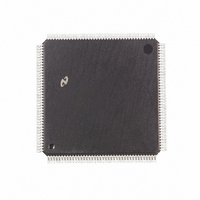
DP83905AVQB National Semiconductor, DP83905AVQB Datasheet - Page 23

DP83905AVQB
Manufacturer Part Number
DP83905AVQB
Description
IC CONTROLR AT/LAN TP IN 160PQFP
Manufacturer
National Semiconductor
Series
AT/LANTIC™r
Datasheet
1.DP83905AVQB.pdf
(80 pages)
Specifications of DP83905AVQB
Controller Type
AT, LAN Twisted-Pair Interface Controller
Voltage - Supply
4.75 V ~ 5.25 V
Current - Supply
100mA
Operating Temperature
0°C ~ 70°C
Mounting Type
Surface Mount
Package / Case
160-BFQFP
Lead Free Status / RoHS Status
Contains lead / RoHS non-compliant
Interface
-
Other names
*DP83905AVQB
Available stocks
Company
Part Number
Manufacturer
Quantity
Price
Company:
Part Number:
DP83905AVQB
Manufacturer:
Texas Instruments
Quantity:
10 000
Part Number:
DP83905AVQB
Manufacturer:
NS/国半
Quantity:
20 000
4 0 Functional Description
Status Information
Status information is provided by the AT LANTIC Controller
on the RXLED TXLED COLED and POL outputs as de-
scribed in the pin description table These outputs are suit-
able for driving status LED’s as shown in Figure 17 All out-
puts are open drain
Recommended integrated Filter-Transformer-choke mod-
ules
4 9 ENCODER DECODER (ENDEC) MODULE
The ENDEC consists of four main logical blocks
a The oscillator generates the 10 MHz transmit clock sig-
b The Manchester encoder accepts NRZ data from the
c The Manchester decoder receives Manchester data from
d The collision translator indicates to the controller the
Oscillator
The oscillator is controlled by a 20 MHz parallel resonant
crystal connected between X1 and X2 or by an external
clock on X1 The 20 MHz output of the oscillator is divided
by 2 to generate the 10 MHz transmit clock for the control-
ler The oscillator also provides internal clock signals to the
encoding and decoding circuits
CRYSTAL OPERATION
If the crystal used with the internal oscillator circuit is not
properly selected the AT LANTIC Controller oscillator may
not reliably start oscillation under all conditions
If this occurs it could be deceiving to a designer since his
prototypes may work fine However when the designer
does qualification testing or starts production he may en-
counter a higher than expected board yield loss due to the
oscillator not starting The AT LANTIC Controller’s oscilla-
tor
AT LANTIC Controller’s oscillator also clocks the twisted
pair interface block If the oscillator does not start the
AT LANTIC Controller will not be able to transmit or re-
ceive
If a crystal is connected to the AT LANTIC Controller it is
recommended that the circuit shown in Figure 19 be used
and that the components used meet the following
Crystal XT1 AT cut parallel resonant crystal
The recommended values for capacitors C1 and C2 are
26 pF minus the board capacitance on that pin Therefore if
both X1 and X2 have 4 pF of board capacitance then a
22 pF capacitor should be used
According to the IEEE 802 3 standard the entire oscillator
circuit (crystal and amplifier) must be accurate to 0 01%
When using a crystal the X2 pin is not guaranteed to pro-
vide a TTL compatible logic output and should not be used
nal for system timing
controller encodes the data to Manchester and trans-
mits the data differentially to the transceiver through the
differential transmit driver
the transceiver converts it to NRZ data and clock puls-
es and sends it to the controller
presence of a valid 10 MHz collision signal to the PLL
1 Pulse Engineering PE65424
2 Valor FL1012 or FL1030
circuit
Series Resistance
Specified Load Capacitance
Accuracy 0 005% (50 ppm)
Typical Load 50 W–75 W
clocks
the
Encoder-Decoder
s
25
s
20 pF
(Continued)
logic
The
23
to drive external standard logic If additional logic needs to
be driven then an external oscillator should be used as
described in the following section
OSCILLATOR MODULE OPERATION
If the designer wishes to use a crystal clock oscillator one
that provides the following should be employed
1 TTL or CMOS output with a 0 01% frequency tolerance
2 40%– 60% duty cycle
The circuit is shown in Figure 20 When using a clock oscil-
lator it is recommended that the designer connect the oscil-
lator output to the X1 pin and leave the X2 pin floating
Manchester Encoder and Differential Driver
The differential transmit pair on the secondary of the em-
ployed transformer drives up to 50 meters of twisted pair
AUI cable These outputs are source followers which require
two 270
The AT LANTIC Controller allows full-step to be compatible
with IEEE 802 3 Transmit
idle state providing zero differential voltage to operate with
transformer coupled loads
Manchester Decoder
The decoder consists of a differential receiver and a PLL to
separate a Manchester encoded data stream into internal
FIGURE 19 Crystal Connection to AT LANTIC
Controller (see text for component values)
pull-down resistors to ground (see Figure 21 )
FIGURE 20 AT LANTIC Controller
Connection for Oscillator Module
a
and Transmit
b
are equal in the
TL F 11498 – 16
TL F 11498 – 17


