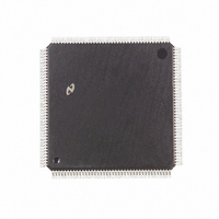
DP83905AVQB National Semiconductor, DP83905AVQB Datasheet - Page 53

DP83905AVQB
Manufacturer Part Number
DP83905AVQB
Description
IC CONTROLR AT/LAN TP IN 160PQFP
Manufacturer
National Semiconductor
Series
AT/LANTIC™r
Datasheet
1.DP83905AVQB.pdf
(80 pages)
Specifications of DP83905AVQB
Controller Type
AT, LAN Twisted-Pair Interface Controller
Voltage - Supply
4.75 V ~ 5.25 V
Current - Supply
100mA
Operating Temperature
0°C ~ 70°C
Mounting Type
Surface Mount
Package / Case
160-BFQFP
Lead Free Status / RoHS Status
Contains lead / RoHS non-compliant
Interface
-
Other names
*DP83905AVQB
Available stocks
Company
Part Number
Manufacturer
Quantity
Price
Company:
Part Number:
DP83905AVQB
Manufacturer:
Texas Instruments
Quantity:
10 000
Part Number:
DP83905AVQB
Manufacturer:
NS/国半
Quantity:
20 000
6 0 Operation of AT LANTIC Controller
Network Management Functions
Network management capabilities are required for mainte-
nance and planning of a local area network
AT LANTIC Controller supports the minimum requirement
for network management in hardware the remaining re-
quirements can be met with software Software alone can
not track during reception of packets CRC errors Frame
Alignment errors and missed packets Figure 36
Since errored packets can be rejected the status associat-
ed with these packets is lost unless the CPU can access the
Receive Status Register before the next packer arrives In
situations where another packet arrives very quickly the
CPU may have no opportunity to do this The AT LANTIC
Controller counts the number of packets with CRC errors
and Frame Alignment errors 8-bit counters have been se-
lected to reduce overhead The counters will generate inter-
rupts whenever their MSBs are set so that a software rou-
tine can accumulate the network statistics and reset the
counter before overflow occurs The counters are sticky so
that when they reach a count of 192 (C0H) counting is halt-
ed An additional counter is provided to count the number of
packets the AT LANTIC Controller misses due to buffer
overflow or being offline
The structure of the counters is shown in Figure 36
Additional information required for network management is
available in the Receive and Transmit Status Registers
Transmit status is available after each transmission for infor-
mation regarding events during transmission
Typically the following statistics might be gathered in soft-
ware
Traffic
Errors
6 6 MEMORY ARBITRATION AND BUS OPERATION
The AT LANTIC Controller will always operate as a slave
device on its peripheral interface to the ISA bus However
on the memory bus the AT LANTIC Controller operates in
three possible modes
1 Bus Master of Local Packet Buffer RAM
2 Bus Slave when accessed by the CPU via the Bus Inter-
3 Idle when no activity is occurring
face
Frames Sent OK
Frames Received OK
Multicast Frames Received
Packets Lost Due to Lack of Resources
Retries Packet
CRC Errors
Alignment Errors
Excessive Collisions
Packet with Length Errors
Heartbeat Failure
FIGURE 36 Tally Counters
TL F 11498– 33
The
53
(Continued)
Upon power-up the AT LANTIC Controller is in an indeter-
minate state
AT LANTIC Controller is a bus slave in the Reset State the
receiver and transmitter are both disabled in this state The
reset state can be re-entered under four conditions soft
reset (Stop Command) register reset (reset port in I O
mode bit in Control Register 1 in shared memory mode)
hard reset (RESET input) or an error that shuts down the
receiver or transmitter (FIFO underflow or overflow receive
buffer ring overflow)
After initialization of registers the AT LANTIC Controller is
issued a Start command and the AT LANTIC Controller en-
ters Idle state Until the DMA is required the AT LANTIC
Controller remains in idle state
The idle state is exited and the AT LANTIC Controller will
drive the local memory bus when a request from the FIFO in
the DP8390 (NIC) core causes the memory bus interface
logic to issue a read or write operation such as when the
AT LANTIC Controller is transmitting or receiving data
In I O mode the NIC Core’s Remote DMA also requests
access from the memory bus When software programs an
I O mode data transfer between the CPU and the buffer
RAM the Remote DMA controls this request
In Shared Memory Mode the memory bus is accessed via
the CPU interface directly
All Local DMA transfers are burst transfers the DMA will
transfer an exact burst of bytes programmed in the Data
Configuration Register (DCR) then relinquish the memory
bus If there are remaining bytes in the FIFO the next burst
will not be initiated until the FIFO threshold is exceeded
I O Mode Operation
In I O mode the AT LANTIC Controller transfers data to
and from the packet buffer RAM by utilizing the Remote
DMA logic which is programmed by the main system CPU to
transfer data through the AT LANTIC Controller’s internal
data port register
FIGURE 37 DP8390 Core Bus States
After receiving a hardware reset the
TL F 11498 – 34


