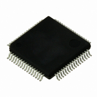
VSC8601XKN Vitesse Semiconductor Corp, VSC8601XKN Datasheet - Page 7

VSC8601XKN
Manufacturer Part Number
VSC8601XKN
Description
IC PHY 10/100/1000 64-EP-LQFP
Manufacturer
Vitesse Semiconductor Corp
Type
PHY Transceiverr
Specifications of VSC8601XKN
Number Of Drivers/receivers
1/1
Protocol
Gigabit Ethernet
Voltage - Supply
2.5V, 3.3V
Mounting Type
Surface Mount
Package / Case
64-LQFP Exposed Pad, 64-eLQFP, 64-HLQFP
Case
TQFP
Dc
06+
Lead Free Status / RoHS Status
Lead free / RoHS Compliant
Other names
907-1028
Available stocks
Company
Part Number
Manufacturer
Quantity
Price
Company:
Part Number:
VSC8601XKN
Manufacturer:
KYOCERA/AVX
Quantity:
20 000
Company:
Part Number:
VSC8601XKN
Manufacturer:
VITESSE
Quantity:
1 235
Company:
Part Number:
VSC8601XKN
Manufacturer:
Vitesse Semiconductor Corporation
Quantity:
10 000
Part Number:
VSC8601XKN
Manufacturer:
VITESSE
Quantity:
20 000
Tables
Revision 4.1
September 2009
Table 1.
Table 2.
Table 3.
Table 4.
Table 5.
Table 6.
Table 7.
Table 8.
Table 9.
Table 10.
Table 11.
Table 12.
Table 13.
Table 14.
Table 15.
Table 16.
Table 17.
Table 18.
Table 19.
Table 20.
Table 21.
Table 22.
Table 23.
Table 24.
Table 25.
Table 26.
Table 27.
Table 28.
Table 29.
Table 30.
Table 31.
Table 32.
Table 33.
Table 34.
Table 35.
Table 36.
Table 37.
Table 38.
Table 39.
Table 40.
Table 41.
Table 42.
Table 43.
Table 44.
Table 45.
Table 46.
Table 47.
Table 48.
Table 49.
Table 50.
Table 51.
Table 52.
Table 53.
Interface and Media ................................................................................... 17
Supported MDI Pair Combinations ................................................................ 21
LED Mode and Function Summary ................................................................ 28
JTAG Device Identification Register Description .............................................. 35
JTAG Interface Instruction Codes ................................................................. 35
IEEE 802.3 Standard Registers .................................................................... 38
Main Registers ........................................................................................... 38
Mode Control, Address 0 (0x00)................................................................... 39
Mode Status, Address 1 (0x01) .................................................................... 40
Identifier 1, Address 2 (0x02)...................................................................... 41
Identifier 2, Address 3 (0x03)...................................................................... 41
Device Auto-Negotiation Advertisement, Address 4 (0x04) .............................. 41
Auto-Negotiation Link Partner Ability, Address 5 (0x05)................................... 42
Auto-Negotiation Expansion, Address 6 (0x06)............................................... 43
Auto-Negotiation Next Page Transmit, Address 7 (0x07) .................................. 43
Auto-Negotiation LP Next Page Receive, Address 8 (0x08) ............................... 44
1000BASE-T Control, Address 9 (0x09) ......................................................... 44
1000BASE-T Status, Address 10 (0x0A) ........................................................ 45
1000BASE-T Status Extension 1, Address 15 (0x0F) ....................................... 45
100BASE-TX Status Extension, Address 16 (0x10) .......................................... 46
1000BASE-T Status Extension 2, Address 17 (0x11) ....................................... 46
Bypass Control, Address 18 (0x12)............................................................... 47
Receive Error Counter, Address 19 (0x13) ..................................................... 48
False Carrier Sense Counter, Address 20 (0x14) ............................................. 48
Disconnect Counter, Address 21 (0x15)......................................................... 49
Extended Control and Status, Address 22 (0x16) ........................................... 49
Extended PHY Control 1, Address 23 (0x17) .................................................. 50
Extended PHY Control 2, Address 24 (0x18) .................................................. 50
Interrupt Mask, Address 25 (0x19)............................................................... 51
Interrupt Status, Address 26 (0x1A)............................................................. 52
LED Control, Address 27 (0x1B)................................................................... 52
Auxiliary Control and Status, Address 28 (0x1C) ............................................ 53
Delay Skew Status, Address = 29 (0x1D)...................................................... 54
Extended Registers Page Space.................................................................... 55
Extended Page Access, Address 31 (0x1F)..................................................... 56
Enhanced LED Method Select, Address 16E (0x10) ......................................... 56
Available LED Mode Settings........................................................................ 56
Enhanced LED Behavior, Address 17E (0x11) ................................................. 57
CRC Good Counter, Address 18E (0x12) ........................................................ 58
MAC Resistor Calibration Control, Address 19E (0x13)..................................... 58
Extended PHY Control 3, Address 20E (0x14)................................................. 59
EEPROM Interface Status and Control, Address 21E (0x15).............................. 59
EEPROM Read or Write, Address 22E (0x16) .................................................. 60
Extended PHY Control 4, Address 23E (0x17)................................................. 60
Extended PHY Control 5, Address 27E (0x1B) ................................................ 61
RGMII Skew Control, Address 28E (0x1C) ..................................................... 62
EPG Control Register 1, Address 29E (0x1D).................................................. 63
EPG Control Register 2, Address 30E (0x1E) .................................................. 64
CMODE Configuration Pins and Device Functions ............................................ 64
Device Functions and Associated CMODE Pins ................................................ 65
CMODE Resistor Values and Resultant Bit Settings .......................................... 65
EEPROM Configuration Contents................................................................... 67
DC Characteristics for VDD33, VDDIOMAC, or VDDIOMICRO at 3.3 V ................ 69
VSC8601 Datasheet
Contents
Page 7


