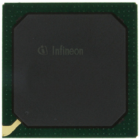
PEB20256E-V21 Infineon Technologies, PEB20256E-V21 Datasheet - Page 121

PEB20256E-V21
Manufacturer Part Number
PEB20256E-V21
Description
IC CONTROLLER INTERFACE 388-BGA
Manufacturer
Infineon Technologies
Datasheet
1.PEB20256E-V21.pdf
(232 pages)
Specifications of PEB20256E-V21
Function
Multichannel Network Interface Controller (MUNICH)
Interface
HDLC, PPP, Serial, TMA
Voltage - Supply
3 V ~ 3.6 V
Current - Supply
200mA
Power (watts)
3W
Operating Temperature
0°C ~ 70°C
Mounting Type
Surface Mount
Package / Case
388-BBGA
Lead Free Status / RoHS Status
Contains lead / RoHS non-compliant
Number Of Circuits
-
Other names
PEB20256E-V21
PEB20256E-V21IN
PEB20256E-V21IN
Available stocks
Company
Part Number
Manufacturer
Quantity
Price
Company:
Part Number:
PEB20256E-V21
Manufacturer:
MAX
Quantity:
63
Company:
Part Number:
PEB20256E-V21
Manufacturer:
Infineon Technologies
Quantity:
10 000
- Current page: 121 of 232
- Download datasheet (3Mb)
7
Since the term “initialization” can have different meanings, the following definition
applies:
Chip Initialization
Generating defined values in all on-chip registers, RAMs (if required), flip-flops etc.
Mode Initialization
Software procedure, that prepares the device to its required operation, i.e. mainly writing
on-chip registers to prepare the device for operation in the respective system
environment.
Operational programming
Software procedures that setup, maintain and shut down operational modes, i.e. initialize
logical channel or maintain framing operations on selected ports.
7.1
Hardware reset
The hardware reset RST has to be applied to the device. Chip input TRST must be
activated prior to or while asserting RST and should be held asserted as long as the
boundary scan operation is not required. System clock must start running during reset.
During reset:
• All I/Os and all outputs are tri-state.
• All registers, state machines, flip-flops etc. are set asynchronously to their reset
• All interrupts are masked.
• The register bit CONF1.STOP is set to ‘1’.
After hardware reset (RST deasserted) system clock CLK is assumed to be running.
Serial clocks must be low/high or running. The PCI and the local bus interface pins go
into their idle state. All serial line outputs are tri-state.
The PCI interface becomes active and depending on input pin SPLOAD starts to read
subsystem ID/subsystem vendor ID and Memory commands out of external EEPROM
via the SPI interface. The serial clock is derived from the PCI clock. As long as this
procedure is active, the PCI interface answers all accesses with retry. After the PCI
interface has finished its self initialization it can be configured with PCI configuration
cycles.
In parallel to PCI self initialization the internal modules start their RAM initialization. As
long as the RAM initialization is running the internal modules indicate this condition with
Data Sheet
values and all internal modules are set to their initial state.
Reset and Initialization procedure
Chip Initialization
121
Reset and Initialization procedure
PEB 20256 E
PEF 20256 E
04.2001
Related parts for PEB20256E-V21
Image
Part Number
Description
Manufacturer
Datasheet
Request
R

Part Number:
Description:
Manufacturer:
Infineon Technologies AG
Datasheet:

Part Number:
Description:
Manufacturer:
Infineon Technologies AG
Datasheet:

Part Number:
Description:
Manufacturer:
Infineon Technologies AG
Datasheet:

Part Number:
Description:
Manufacturer:
Infineon Technologies AG
Datasheet:

Part Number:
Description:
Manufacturer:
Infineon Technologies AG
Datasheet:

Part Number:
Description:
Manufacturer:
Infineon Technologies AG
Datasheet:

Part Number:
Description:
Manufacturer:
Infineon Technologies AG
Datasheet:

Part Number:
Description:
16-bit microcontroller with 2x2 KByte RAM
Manufacturer:
Infineon Technologies AG
Datasheet:

Part Number:
Description:
NPN silicon RF transistor
Manufacturer:
Infineon Technologies AG
Datasheet:

Part Number:
Description:
NPN silicon RF transistor
Manufacturer:
Infineon Technologies AG
Datasheet:

Part Number:
Description:
NPN silicon RF transistor
Manufacturer:
Infineon Technologies AG
Datasheet:

Part Number:
Description:
NPN silicon RF transistor
Manufacturer:
Infineon Technologies AG
Datasheet:

Part Number:
Description:
Si-MMIC-amplifier in SIEGET 25-technologie
Manufacturer:
Infineon Technologies AG
Datasheet:

Part Number:
Description:
IGBT Power Module
Manufacturer:
Infineon Technologies AG
Datasheet:

Part Number:
Description:
IC for switching-mode power supplies
Manufacturer:
Infineon Technologies AG
Datasheet:


