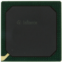
PEB20256E-V21 Infineon Technologies, PEB20256E-V21 Datasheet - Page 64

PEB20256E-V21
Manufacturer Part Number
PEB20256E-V21
Description
IC CONTROLLER INTERFACE 388-BGA
Manufacturer
Infineon Technologies
Datasheet
1.PEB20256E-V21.pdf
(232 pages)
Specifications of PEB20256E-V21
Function
Multichannel Network Interface Controller (MUNICH)
Interface
HDLC, PPP, Serial, TMA
Voltage - Supply
3 V ~ 3.6 V
Current - Supply
200mA
Power (watts)
3W
Operating Temperature
0°C ~ 70°C
Mounting Type
Surface Mount
Package / Case
388-BBGA
Lead Free Status / RoHS Status
Contains lead / RoHS non-compliant
Number Of Circuits
-
Other names
PEB20256E-V21
PEB20256E-V21IN
PEB20256E-V21IN
Available stocks
Company
Part Number
Manufacturer
Quantity
Price
Company:
Part Number:
PEB20256E-V21
Manufacturer:
MAX
Quantity:
63
Company:
Part Number:
PEB20256E-V21
Manufacturer:
Infineon Technologies
Quantity:
10 000
- Current page: 64 of 232
- Download datasheet (3Mb)
When the MUNICH256 completes a data section, which included the end of a frame
(C bit and FE bit are set), or when the MUNICH256 branches to a new linked list due to
a 'Receive Abort/Branch' command the status information bits RAB, ILEN, CRC, RFOD
and MFL are updated as part of the receive status update. In the abort scenario, the C
bit will always be set. Bit FE will be set only, if the particular channel operates in HDLC
or PPP mode.
RAB
ILEN
CRC
RFOD
MFL
4.3.3
The data management unit receive transfers data for each of the 256 logical receive
channels from the internal receive buffer to the data sections of the corresponding
channel. To fulfill the task it has to be initialized for operation, which is described in
“Channel Programming / Reprogramming Concept” on Page 1 1 5
the channel information for the data management unit is the address pointer to the first
receive descriptor, the channel interrupt queue and the channel interrupt mask.
The first receive descriptor of a channel is fetched from system memory and stored in
the chip internal channel database the first time the receive buffer requests a data
transfer for the channel. The descriptor contains a pointer to the data section, the size of
the provided data section and a pointer to the next receive descriptor.
The data transfer is requested as soon as a programmed receive buffer threshold is
reached. This threshold is programmed during channel setup on a per channel basis.
Task of the data management unit is to calculate the maximum number of bytes that can
Data Sheet
Data Management Unit Receive
Receive Abort
This bit is set when
•the incoming serial data stream contained an abort sequence, or
•an incoming frame was aborted by the command ’Receive Abort/
•when a channel is switched off while a frame is being received.
Illegal length
This bit is set, when the length of the incoming data packet was not a
multiple of eight bits.
CRC Error
This bit is set, when the checksum of an incoming data packet was
different to the internally calculated checksum.
Receive Frame Overflow
This bit is set, when a receive buffer overflow occurred during data
reception.
Maximum Frame Length
This bit is set, when the length of the incoming data packet exceeded the
value programmed in CONF1.MFL.
Branch’, or
64
Functional Description
. Relevant part of
PEB 20256 E
PEF 20256 E
04.2001
Related parts for PEB20256E-V21
Image
Part Number
Description
Manufacturer
Datasheet
Request
R

Part Number:
Description:
Manufacturer:
Infineon Technologies AG
Datasheet:

Part Number:
Description:
Manufacturer:
Infineon Technologies AG
Datasheet:

Part Number:
Description:
Manufacturer:
Infineon Technologies AG
Datasheet:

Part Number:
Description:
Manufacturer:
Infineon Technologies AG
Datasheet:

Part Number:
Description:
Manufacturer:
Infineon Technologies AG
Datasheet:

Part Number:
Description:
Manufacturer:
Infineon Technologies AG
Datasheet:

Part Number:
Description:
Manufacturer:
Infineon Technologies AG
Datasheet:

Part Number:
Description:
16-bit microcontroller with 2x2 KByte RAM
Manufacturer:
Infineon Technologies AG
Datasheet:

Part Number:
Description:
NPN silicon RF transistor
Manufacturer:
Infineon Technologies AG
Datasheet:

Part Number:
Description:
NPN silicon RF transistor
Manufacturer:
Infineon Technologies AG
Datasheet:

Part Number:
Description:
NPN silicon RF transistor
Manufacturer:
Infineon Technologies AG
Datasheet:

Part Number:
Description:
NPN silicon RF transistor
Manufacturer:
Infineon Technologies AG
Datasheet:

Part Number:
Description:
Si-MMIC-amplifier in SIEGET 25-technologie
Manufacturer:
Infineon Technologies AG
Datasheet:

Part Number:
Description:
IGBT Power Module
Manufacturer:
Infineon Technologies AG
Datasheet:

Part Number:
Description:
IC for switching-mode power supplies
Manufacturer:
Infineon Technologies AG
Datasheet:


