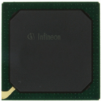
PEB20256E-V21 Infineon Technologies, PEB20256E-V21 Datasheet - Page 55

PEB20256E-V21
Manufacturer Part Number
PEB20256E-V21
Description
IC CONTROLLER INTERFACE 388-BGA
Manufacturer
Infineon Technologies
Datasheet
1.PEB20256E-V21.pdf
(232 pages)
Specifications of PEB20256E-V21
Function
Multichannel Network Interface Controller (MUNICH)
Interface
HDLC, PPP, Serial, TMA
Voltage - Supply
3 V ~ 3.6 V
Current - Supply
200mA
Power (watts)
3W
Operating Temperature
0°C ~ 70°C
Mounting Type
Surface Mount
Package / Case
388-BBGA
Lead Free Status / RoHS Status
Contains lead / RoHS non-compliant
Number Of Circuits
-
Other names
PEB20256E-V21
PEB20256E-V21IN
PEB20256E-V21IN
Available stocks
Company
Part Number
Manufacturer
Quantity
Price
Company:
Part Number:
PEB20256E-V21
Manufacturer:
MAX
Quantity:
63
Company:
Part Number:
PEB20256E-V21
Manufacturer:
Infineon Technologies
Quantity:
10 000
- Current page: 55 of 232
- Download datasheet (3Mb)
4.1.5
A remote channel loop can be switched for one logical channel at a time. Incoming serial
data located in the receive payload of one port is mirrored to the corresponding transmit
channel (same channel number). An internal jitter attenuator compensates jitter between
receive clock and transmit clock. Nevertheless, the average clock rate of the receive port
and the transmit port must be the same. After first activation of the loop 32 receive bytes
are written to the loop FIFO. Then the time slot assigner starts reading data bytes out of
the loop buffer and inserts them into the transmit data path. Hence, the initial distance
between the FIFO read pointer and the FIFO write pointer is 32 bytes. Due to a receive/
transmit clock jitter the read pointer may move towards the write pointer. In case the
distance between write pointer and read pointer is equal plus/minus 1 byte a slip of the
read pointer will occur.
In channelized and unchannelized mode the transmit and receive masks of all time slots
belonging to the looped channel must be the same. The aggregate bit rate of the transmit
section and the aggregate bit rate of the receive section has to be identical.
In receive direction incoming data of the selected channel is stored in the loop buffer. In
transmit direction data is clocked out of the loop buffer and transmitted in the time slots
of the selected channel. Received data is processed normally.
The remote channel loop can also be used to loop the complete payload except the ’F’-
bit (T1). Therefore one logical channel must be setup which includes all payload time
slots.
•
Figure 4-4
Data Sheet
RCLK(x)
TCLK(x)
RSP(x)
TSP(x)
RD(x)
TD(x)
Remote Channel Loopback
Remote Channel Loop
Transmit
Receive
Port
Port
Assigner
Assigner
Timeslot
Timeslot
55
Buffer
Loop
+
Functional Description
Machine
Machine
Protocol
Protocol
PEB 20256 E
PEF 20256 E
04.2001
From
PCI
PCI
To
Related parts for PEB20256E-V21
Image
Part Number
Description
Manufacturer
Datasheet
Request
R

Part Number:
Description:
Manufacturer:
Infineon Technologies AG
Datasheet:

Part Number:
Description:
Manufacturer:
Infineon Technologies AG
Datasheet:

Part Number:
Description:
Manufacturer:
Infineon Technologies AG
Datasheet:

Part Number:
Description:
Manufacturer:
Infineon Technologies AG
Datasheet:

Part Number:
Description:
Manufacturer:
Infineon Technologies AG
Datasheet:

Part Number:
Description:
Manufacturer:
Infineon Technologies AG
Datasheet:

Part Number:
Description:
Manufacturer:
Infineon Technologies AG
Datasheet:

Part Number:
Description:
16-bit microcontroller with 2x2 KByte RAM
Manufacturer:
Infineon Technologies AG
Datasheet:

Part Number:
Description:
NPN silicon RF transistor
Manufacturer:
Infineon Technologies AG
Datasheet:

Part Number:
Description:
NPN silicon RF transistor
Manufacturer:
Infineon Technologies AG
Datasheet:

Part Number:
Description:
NPN silicon RF transistor
Manufacturer:
Infineon Technologies AG
Datasheet:

Part Number:
Description:
NPN silicon RF transistor
Manufacturer:
Infineon Technologies AG
Datasheet:

Part Number:
Description:
Si-MMIC-amplifier in SIEGET 25-technologie
Manufacturer:
Infineon Technologies AG
Datasheet:

Part Number:
Description:
IGBT Power Module
Manufacturer:
Infineon Technologies AG
Datasheet:

Part Number:
Description:
IC for switching-mode power supplies
Manufacturer:
Infineon Technologies AG
Datasheet:


