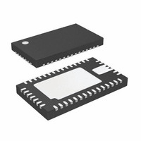
LTC3577EUFF#PBF Linear Technology, LTC3577EUFF#PBF Datasheet - Page 22

LTC3577EUFF#PBF
Manufacturer Part Number
LTC3577EUFF#PBF
Description
IC PWR MANAGEMENT HANDHELD 44QFN
Manufacturer
Linear Technology
Datasheet
1.LTC3577EUFFPBF.pdf
(54 pages)
Specifications of LTC3577EUFF#PBF
Applications
Handheld/Mobile Devices
Voltage - Supply
4.35 V ~ 5.5 V
Operating Temperature
-40°C ~ 85°C
Mounting Type
Surface Mount
Package / Case
44-QFN
Lead Free Status / RoHS Status
Lead free / RoHS Compliant
Current - Supply
-
Available stocks
Company
Part Number
Manufacturer
Quantity
Price
OPERATION
LTC3577/LTC3577-1
Ideal Diode from BAT to V
The LTC3577 has an internal ideal diode as well as a con-
troller for an optional external ideal diode. Both the internal
and the external ideal diodes respond quickly whenever
V
input current limit, additional current will be pulled from
the battery via the ideal diodes. Furthermore, if power to
V
regulator) is removed, then all of the application power
will be provided by the battery via the ideal diodes. The
ideal diodes are fast enough to keep V
signifi cantly with just the recommended output capacitor
(see Figure 2). The ideal diode consists of a precision ampli-
fi er that enables an on-chip P-channel MOSFET whenever
the voltage at V
the voltage at BAT. The resistance of the internal ideal
diode is approximately 200mΩ. If this is suffi cient for
the application, then no external components are neces-
sary. However, if lower resistance is needed, an external
P-channel MOSFET can be added from BAT to V
IDGATE pin of the LTC3577 drives the gate of the external
P-channel MOSFET for automatic ideal diode control. The
source of the MOSFET should be connected to V
the drain should be connected to BAT. Capable of driving a
1nF load, the IDGATE pin can control an external P-channel
MOSFET having extremely low on-resistance.
22
OUT
BUS
LOAD
I
V
VOUT
I
OUT
BAT
–500mA
500mA
(USB) or V
drops below BAT. If the load increases beyond the
4.0V
3.8V
3.6V
1A
0A
0
V
V
5x MODE
C
Figure 2. Ideal Diode Transient Response
BAT
BUS
OUT
CHARGE
DISCHARGE
= 3.8V
= 5V
= 10μF
OUT
OUT
is approximately 15mV (V
(external wall power or high voltage
10μs/DIV
OUT
OUT
from dropping
3577 F02
FWD
OUT
OUT
) below
. The
and
Using the WALL Pin to Detect the Presence of an
External Power Source
The WALL input pin can be used to identify the presence
of an external power source (particularly one that is not
subject to a fi xed current limit like the USB V
Typically, such a power supply would be a 5V wall adapter
output or the low voltage output of a high voltage buck
regulator (specifi cally, LT3480, LT3653 or LT3505). When
the wall adapter output (or buck regulator output) is con-
nected directly to the WALL pin, and the voltage exceeds
the WALL pin threshold, the USB power path (from V
to V
will be pulled low. In order for the presence of an external
power supply to be acknowledged, both of the following
conditions must be satisfi ed:
1. The WALL pin voltage must exceed approximately
2. The WALL pin voltage must be greater than 75mV above
The input power path (between V
enabled and the ACPR pin is pulled high when either of
the following conditions is met:
1. The WALL pin voltage falls to within 25mV of the BAT
2. The WALL pin voltage falls below 3.2V.
Each of these thresholds is suitably fi ltered in time to
prevent transient glitches on the WALL pin from falsely
triggering an event.
External HV Buck Control Through the V
The WALL, ACPR and V
with an external high voltage buck regulator such as the
LT3480, LT3505 or LT3653 to provide power directly to the
V
complete list of approved high voltage buck regulators).
When the WALL pin voltage exceeds 4.3V, V
circuitry is enabled and drives the V
LT3505 or LT3653. The V
so that no compensation components are required on the
V
larger of (BAT + 300mV) or 3.6V as shown in Figure 6.
OUT
C
4.3V.
the BAT pin voltage.
pin voltage.
node. The voltage at the V
OUT
pin as shown in Figures 3 to 5 (Consult factory for
) will be disconnected. Furthermore, the ACPR pin
C
C
pins can be used in conjunction
pin control circuitry is designed
OUT
pin is regulated to the
BUS
C
pin of the LT3480,
and V
C
Pin
C
BUS
OUT
pin control
) is re-
input).
3577fa
BUS


