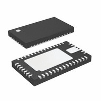
LTC3577EUFF#PBF Linear Technology, LTC3577EUFF#PBF Datasheet - Page 25

LTC3577EUFF#PBF
Manufacturer Part Number
LTC3577EUFF#PBF
Description
IC PWR MANAGEMENT HANDHELD 44QFN
Manufacturer
Linear Technology
Datasheet
1.LTC3577EUFFPBF.pdf
(54 pages)
Specifications of LTC3577EUFF#PBF
Applications
Handheld/Mobile Devices
Voltage - Supply
4.35 V ~ 5.5 V
Operating Temperature
-40°C ~ 85°C
Mounting Type
Surface Mount
Package / Case
44-QFN
Lead Free Status / RoHS Status
Lead free / RoHS Compliant
Current - Supply
-
Available stocks
Company
Part Number
Manufacturer
Quantity
Price
OPERATION
The feedback network of the high voltage buck regulator
should be set to generate an output voltage higher than
4.4V (be sure to include the output voltage tolerance
of the buck regulator). The V
overdrives the local V
age buck. Therefore, once the V
output voltage is set independent of the buck regulator
feedback network.
This technique provides a signifi cant effi ciency advantage
over the use of a 5V buck to drive the battery charger. With
a simple 5V buck output driving V
effi ciency is approximately:
where η
regulator and 5V is the output voltage of the buck regu-
lator. With a typical buck effi ciency of 87% and a typical
battery voltage of 3.8V, the total battery charger effi ciency
is approximately 66%. Assuming a 1A charge current,
this works out to nearly 2W of power dissipation just to
charge the battery!
With the V
is approximately:
With the same assumptions as above, the total battery
charger effi ciency is approximately 81%. This example
works out to just 900mW of power dissipation. For applica-
tions, component selection and board layout information
beyond those listed here please refer to the respective
high voltage buck regulator data sheet.
Suspend Mode
When I
LTC3577 enters suspend mode to comply with the USB
specifi cation. In this mode, the power path between V
and V
V
is available to drive WALL and V
connected to V
connected to BAT.
BUS
η
η
CHARGER
CHARGER
OUT
input current to 50μA. If no other power source
LIM0
BUCK
is put in a high impedance state to reduce the
C
control technique, battery charger effi ciency
is pulled low and I
= η
= η
is the effi ciency of the high voltage buck
OUT
BUCK
BUCK
is supplied through the ideal diodes
C
•
•
control of the external high volt-
0.3V + V
V
5V
BAT
V
BAT
C
C
control of the LTC3577
LIM1
BAT
control is enabled, the
OUT
OUT
is pulled high the
, the system load
, battery charger
BUS
V
Current Limit (UVCL)
An internal undervoltage lockout circuit monitors V
and keeps the input current limit circuitry off until V
rises above the rising UVLO threshold (3.8V) and at least
50mV above V
input current limit if V
V
drawn from the battery via the ideal diode. To minimize the
possibility of oscillation in and out of UVLO when using
resistive input supplies, the input current limit is reduced
as V
Battery Charger
The LTC3577 includes a constant-current/constant-volt-
age battery charger with automatic recharge, automatic
termination by safety timer, low voltage trickle charging,
bad cell detection and thermistor sensor input for out of
temperature charge pausing. When a battery charge cycle
begins, the battery charger fi rst determines if the battery
is deeply discharged. If the battery voltage is below V
typically 2.85V, an automatic trickle charge feature sets the
battery charge current to 10% of the programmed value.
If the low voltage persists for more than one-half hour, the
battery charger automatically terminates. Once the battery
voltage is above 2.85V, the battery charger begins charging
in full power constant current mode. The current delivered
to the battery will try to reach 1000V/R
on available input power and external load conditions, the
battery charger may or may not be able to charge at the
full programmed rate. The external load will always be
prioritized over the battery charge current. The USB cur-
rent limit programming will always be observed and only
additional current will be available to charge the battery.
When system loads are light, battery charge current will
be maximized.
Charge Termination
The battery charger has a built-in safety timer. When the
battery voltage approaches the fl oat voltage, the charge
current begins to decrease as the LTC3577 enters constant
voltage mode. Once the battery charger detects that it
has entered constant voltage mode, the four hour safety
BUS
OUT
BUS
. When this happens, system power at V
Undervoltage Lockout (UVLO) and Undervoltage
falls below 4.45V (typ).
OUT
LTC3577/LTC3577-1
. Hysteresis on the UVLO turns off the
BUS
drops below 3.7V or 50mV below
PROG
. Depending
OUT
25
will be
TRKL
3577fa
BUS
BUS
,


