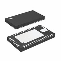
LTC3577EUFF#PBF Linear Technology, LTC3577EUFF#PBF Datasheet - Page 27

LTC3577EUFF#PBF
Manufacturer Part Number
LTC3577EUFF#PBF
Description
IC PWR MANAGEMENT HANDHELD 44QFN
Manufacturer
Linear Technology
Datasheet
1.LTC3577EUFFPBF.pdf
(54 pages)
Specifications of LTC3577EUFF#PBF
Applications
Handheld/Mobile Devices
Voltage - Supply
4.35 V ~ 5.5 V
Operating Temperature
-40°C ~ 85°C
Mounting Type
Surface Mount
Package / Case
44-QFN
Lead Free Status / RoHS Status
Lead free / RoHS Compliant
Current - Supply
-
Available stocks
Company
Part Number
Manufacturer
Quantity
Price
OPERATION
High value, low ESR multilayer ceramic chip capacitors
reduce the constant-voltage loop phase margin, possibly
resulting in instability. Ceramic capacitors up to 22μF may
be used in parallel with a battery, but larger ceramics should
be decoupled with 0.2Ω to 1Ω of series resistance.
In constant-current mode, the PROG pin is in the feed-
back loop rather than the battery voltage. Because of the
additional pole created by any PROG pin capacitance,
capacitance on this pin must be kept to a minimum. With
no additional capacitance on the PROG pin, the battery
charger is stable with program resistor values as high
as 25k. However, additional capacitance on this node
reduces the maximum allowed program resistor. The pole
frequency at the PROG pin should be kept above 100kHz.
Therefore, if the PROG pin has a parasitic capacitance,
C
the maximum resistance value for R
NTC Thermistor and Battery Voltage Reduction
The battery temperature is measured by placing a nega-
tive temperature coeffi cient (NTC) thermistor close to
the battery pack. To use this feature connect the NTC
thermistor, R
bias resistor, R
be a 1% resistor with a value equal to the value of the
chosen NTC thermistor at 25°C (R25). The LTC3577 will
pause charging when the resistance of the NTC thermistor
drops to 0.54 times the value of R25 or approximately 54k
(for a Vishay “Curve 1” thermistor, this corresponds to
approximately 40°C). If the battery charger is in constant
voltage (fl oat) mode, the safety timer also pauses until the
thermistor indicates a return to a valid temperature. As the
temperature drops, the resistance of the NTC thermistor
rises. The LTC3577 is also designed to pause charging
when the value of the NTC thermistor increases to 3.17
times the value of R25. For a Vishay “Curve 1” thermistor
this resistance, 317k, corresponds to approximately 0°C.
The hot and cold comparators each have approximately
3°C of hysteresis to prevent oscillation about the trip point.
The typical NTC circuit is shown in Figure 8.
PROG
R
PROG
, the following equation should be used to calculate
≤
2π • 100kHz • C
NTC
NOM
, between the NTC pin and ground and a
, from NTCBIAS to NTC. R
1
PROG
PROG
:
NOM
should
To improve safety and reliability the battery voltage is re-
duced when the battery temperature becomes excessively
high. When the resistance of the NTC thermistor drops to
about 0.35 times the value of R25 or approximately 35k
(for a Vishay “Curve 1” thermistor, this corresponds to
approximately 50°C) the NTC enables circuitry to moni-
tor the battery voltage. If the battery voltage is above the
battery discharge threshold (about 3.9V) then the battery
discharge circuitry is enabled and draws about 140mA
from the battery when V
V
threshold the discharge current is linearly reduced until
it reaches 0mA at which point the discharge circuitry is
disabled. Reducing the discharge current in this fashion
keeps the circuit from causing oscillations on V
to battery ESR.
When the charger is disabled an internal watchdog timer
samples the NTC thermistor for about 150μs every 150ms
and will enable the battery monitoring circuitry if the bat-
tery temperature exceeds the NTC TOO_HOT threshold.
If adding a capacitor to the NTC pin for fi ltering the time
constant must be much less than 150μs so that the NTC
pin can settle to its fi nal value during the sampling period.
A time constant of less than 10μs is recommended. Once
the battery monitoring circuitry is enabled it will remain
enabled and monitoring the battery voltage until the battery
BUS
= 5V. As the battery voltage approaches the discharge
NTCBIAS
R
100k
R
100k
NOM
NTC
34
35
NTC
Figure 8. Typical NTC Thermistor Circuit
0.35 • NTCBIAS
0.26 • NTCBIAS
0.76 • NTCBIAS
LTC3577/LTC3577-1
BUS
= 0V and about 180mA when
–
–
–
NTC BLOCK
+
+
+
TOO_COLD
TOO_HOT
BATTERY
OVERTEMP
LTC3577
BAT
3577 F08
27
3577fa
due


