KP-F1 Panduit Corp, KP-F1 Datasheet - Page 255
KP-F1
Manufacturer Part Number
KP-F1
Description
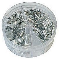
KIT FERRULE NONINS AWG22-14
Manufacturer
Panduit Corp
Series
Pan-Term®r
Type
Ferrule kitr
Datasheet
1.KP-FSD1.pdf
(1040 pages)
Specifications of KP-F1
Kit Type
Ferrule - Wire End
Values
370 pcs - Assorted Non-Insulated 22 ~ 14 AWG Ferrules
Kit Contents
500 Pieces Of F75-6, 400 Pieces Of F76-6 & F77-6, 300 Pieces Of F78-7, 200 Pieces Of F80-7
Lead Free Status / Rohs Status
Lead free / RoHS Compliant


• Narrow slot/finger design provides more slots to fit the spacing of
• Material: Lead-free PVC
• UL recognized continuous use temperature: 122°F (50°C)
• UL 94 flammability rating of V-0
high-density terminal blocks and other hardware
Multiple slot restrictors present with
2" and greater duct wall height.
To order cover with protective film
add “-F” to part number. 6" cover
not available with film.
H
.20 TYP [5.0]
W
.50 TYP [12.7]
Panduct
®
Type F Narrow Slot Wiring Duct
Base
Part Number
F.5X.5LG6
F.5X1LG6
F.75X.75LG6
F.75X1.5LG6
F1X1LG6
F1X1.5LG6
F1X2LG6
F1X3LG6
F1X4LG6
F1.5X1LG6
F1.5X1.5LG6
F1.5X2LG6
F1.5X3LG6
F1.5X4LG6
F2X1LG6
F2X1.5LG6
F2X2LG6
F2X3LG6
F2X4LG6
F2X5LG6
F2.5X3LG6
F3X1LG6
F3X2LG6
F3X3LG6
F3X4LG6
F3X5LG6
F4X2LG6
F4X3LG6
F4X4LG6
F4X5LG6
F6X4LG6
Part number shown for LG (Light Gray). For other color availability see color selection guide, page C1.48.
Base and cover sold separately.
*“H” dimension includes duct and cover.
For technical assistance in the U.S., call 866-405-6654 (outside the U.S., see inside back cover for directory)
ELECTRICAL SOLUTIONS
0.69 x 0.60
0.69 x 1.06
0.93 x 0.82
0.93 x 1.57
1.26 x 1.13
1.26 x 1.62
1.26 x 2.12
1.26 x 3.12
1.26 x 4.10
1.75 x 1.12
1.75 x 1.62
1.75 x 2.12
1.75 x 3.12
1.75 x 4.10
2.25 x 1.12
2.25 x 1.62
2.25 x 2.12
2.25 x 3.12
2.25 x 4.10
2.25 x 5.10
2.75 x 3.12
3.25 x 1.12
3.25 x 2.12
3.25 x 3.12
3.25 x 4.10
3.25 x 5.10
4.25 x 2.12
4.25 x 3.12
4.25 x 4.10
4.25 x 5.10
6.25 x 4.15
Duct Size (W x H)*
In.
• Conforms with NFPA 79-2007 section 13.3.1 requirement
• Provided with mounting holes
• Base and cover length is 6 feet
for flame retardant material
108.0 x 104.1
108.0 x 129.5
158.8 x 105.4
32.0 x 104.1
44.5 x 104.1
57.2 x 104.1
57.2 x 129.5
82.6 x 104.1
82.6 x 129.5
108.0 x 53.8
108.0 x 79.2
17.5 x 15.2
17.5 x 26.9
23.6 x 20.9
23.6 x 39.9
32.0 x 28.7
32.0 x 41.1
32.0 x 53.8
32.0 x 79.2
44.5 x 28.4
44.5 x 41.1
44.5 x 53.8
44.5 x 79.2
57.2 x 28.4
57.2 x 41.1
57.2 x 53.8
57.2 x 79.2
69.9 x 79.2
82.6 x 28.4
82.6 x 53.8
82.6 x 79.2
mm
0.20
0.20
0.20
0.20
0.20
0.20
0.20
0.20
0.20
0.20
0.20
0.20
0.20
0.20
0.20
0.20
0.20
0.20
0.20
0.20
0.20
0.20
0.20
0.20
0.20
0.20
0.20
0.20
0.20
0.20
0.20
Slot Width
In.
mm
5.0
5.0
5.0
5.0
5.0
5.0
5.0
5.0
5.0
5.0
5.0
5.0
5.0
5.0
5.0
5.0
5.0
5.0
5.0
5.0
5.0
5.0
5.0
5.0
5.0
5.0
5.0
5.0
5.0
5.0
5.0
Part Number
C.75LG6
C.75LG6
C1.5LG6
C1.5LG6
C1.5LG6
C1.5LG6
C1.5LG6
C2.5LG6
C.5LG6
C.5LG6
C1LG6
C1LG6
C1LG6
C1LG6
C1LG6
C2LG6
C2LG6
C2LG6
C2LG6
C2LG6
C2LG6
C3LG6
C3LG6
C3LG6
C3LG6
C3LG6
C4LG6
C4LG6
C4LG6
C4LG6
C6LG6
Cover
Pkg.
Std.
Qty.
6
6
6
6
6
6
6
6
6
6
6
6
6
6
6
6
6
6
6
6
6
6
6
6
6
6
6
6
6
6
6
Base
Ctn.
Qty.
120
120
120
120
120
120
120
120
120
120
120
120
120
120
120
120
120
120
60
60
60
60
60
60
60
60
60
60
60
60
60
Cover
Ctn.
Qty.
120
120
120
120
120
120
120
120
120
120
120
120
120
120
120
120
120
120
120
120
120
120
120
120
120
120
120
120
120
120
120
C1.15
Management
Identification
Accessories
Connectors
Connectors
Grounding
Pre-Printed
& Write-On
Protection
Permanent
Solutions
Cable Ties
Terminals
Lockout/
Overview
Steel Ties
& Safety
Stainless
Raceway
Abrasion
Labeling
Systems
Surface
Markers
Tagout
System
Wiring
Labels
Power
Cable
Cable
Index
Duct
E5.
B1.
B2.
B3.
D1.
D2.
D3.
C1.
C2.
C3.
C4.
E1.
E2.
E3.
E4.
A.
F.