KP-F1 Panduit Corp, KP-F1 Datasheet - Page 731
KP-F1
Manufacturer Part Number
KP-F1
Description
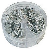
KIT FERRULE NONINS AWG22-14
Manufacturer
Panduit Corp
Series
Pan-Term®r
Type
Ferrule kitr
Datasheet
1.KP-FSD1.pdf
(1040 pages)
Specifications of KP-F1
Kit Type
Ferrule - Wire End
Values
370 pcs - Assorted Non-Insulated 22 ~ 14 AWG Ferrules
Kit Contents
500 Pieces Of F75-6, 400 Pieces Of F76-6 & F77-6, 300 Pieces Of F78-7, 200 Pieces Of F80-7
Lead Free Status / Rohs Status
Lead free / RoHS Compliant


For Use with Class 2 Stranded Copper Conductors
Type LCMD
• Inspection window to visually assure full conductor insertion
• Tin-plated to inhibit corrosion
• UL Listed, UL Recognized, and CSA Certified to 35 KV** and
‡See page D3.83 for tool and die information.
*UL Recognized only.
**Consult cable manufacturer for voltage stress relief instructions with applications greater than 2000 V.
Part
Number
LCMD6-5CD-Q*
LCMD10-6CD-Q
LCMD10-8-Q
LCMD10-00-Q*
LCMD16-6CD-Q*
LCMD16-8-Q*
LCMD16-00-Q*
LCMD25-8CD-Q*
LCMD25-8-Q
LCMD25-10-Q
LCMD25-12-Q
LCMD25-00-Q*
LCMD35-8CD-Q
LCMD35-10-Q
LCMD35-12-Q
LCMD35-00-Q*
LCMD50-10CD-X
LCMD50-10-X
LCMD50-12-X
LCMD50-00-X*
LCMD70-10CD-X
LCMD70-10-X
LCMD70-12-X
LCMD70-00-X*
LCMD95-10CD-X
LCMD95-12-X
LCMD95-14-X
LCMD95-00-X*
temperature rated to 90°C when crimped with Panduit tools
and dies
Metric Conductor, Two-Hole, Standard Barrel with Window Lug
Class 2R (mm²)
Conductor
Copper
4 – 6
Size
10
10
10
16
16
16
25
25
25
25
25
35
35
35
35
50
50
50
50
70
70
70
70
95
95
95
95
Current
(Amps)
Rating
B
30
65
65
65
—
—
—
—
—
—
—
—
—
—
—
—
—
—
—
—
—
—
—
—
—
—
—
—
For technical assistance in the U.S., call 866-405-6654 (outside the U.S., see inside back cover for directory)
N
Hole Size
(mm)
Blank
Blank
Blank
Blank
Blank
Blank
Blank
Stud
STUD HOLE
M10
M12
M10
M12
M10
M10
M12
M10
M10
M12
M10
M12
M14
SPACING
M5
M6
M8
M6
M8
M8
M8
M8
D
INSPECTION
L
WINDOW
ELECTRICAL SOLUTIONS
22.0 – 25.0
22.0 – 25.0
22.0 – 25.0
22.0 – 25.0
22.0 – 25.0
22.0 – 25.0
22.0 – 25.0
22.0 – 25.0
M
Spacing
(mm)
Stud
Hole
44.5
44.5
44.5
44.5
44.5
44.5
44.5
44.5
44.5
44.5
44.5
44.5
44.5
—
—
—
—
—
—
—
I
11.5
11.5
11.5
11.5
13.5
13.5
13.5
13.5
• Product information marked on connector for selection
• Internally beveled wire entry for fast and easy installation
3.8
4.5
4.5
4.4
5.5
5.5
5.5
6.9
6.9
6.9
7.1
7.1
8.2
8.2
8.2
8.2
9.8
9.8
9.8
9.8
ØI
and installation
B
N
10.0
11.0
13.0
14.5
13.0
13.0
15.0
15.5
15.5
15.5
20.0
20.0
15.5
15.5
21.5
21.5
18.0
18.0
23.0
23.0
20.5
20.8
20.8
20.8
24.5
24.5
24.5
24.5
B
STUD HOLE
SPACING
Figure Dimensions (mm)
D
INSPECTION
WINDOW
L
10.3
10.3
10.0
10.0
10.0
14.5
12.3
12.3
14.5
11.5
11.5
14.0
14.5
14.5
14.5
15.0
15.0
15.0
7.8
9.8
8.5
—
—
—
—
—
—
—
M
M
11.5
11.5
10.0
10.0
11.0
11.0
11.5
11.5
13.0
13.5
13.5
6.2
6.0
8.0
6.5
6.5
8.0
8.0
8.0
8.5
8.5
—
—
—
—
—
—
—
N
I
105.0
105.0
105.0
Table continues on page D2.110
52.5
55.8
75.3
75.3
59.5
79.0
81.2
62.0
81.5
81.5
89.5
89.5
67.0
86.5
92.5
92.5
71.5
91.0
94.5
94.5
78.5
98.0
98.0
98.0
85.5
B
L
11.0
14.0
11.0
14.0
11.0
11.0
14.0
11.0
11.0
14.0
11.0
14.0
16.0
ØD
5.5
6.6
9.0
6.6
9.0
9.0
9.0
9.0
—
—
—
—
—
—
—
INSPECTION
L
WINDOW
Die Index
Panduit
No.‡
P10
P21
P21
P21
P24
P24
P24
P29
P29
P29
P29
P29
P29
P29
P29
P29
P37
P37
P37
P37
P45
P45
P45
P45
P54
P54
P54
P54
Pkg.
Std.
Qty.
25
25
25
25
25
25
25
25
25
25
25
25
25
25
25
25
10
10
10
10
10
10
10
10
10
10
10
10
I
D2.109
Management
Identification
Accessories
Connectors
Connectors
Grounding
Pre-Printed
& Write-On
Protection
Permanent
Solutions
Cable Ties
Terminals
Lockout/
Overview
Steel Ties
& Safety
Stainless
Raceway
Abrasion
Labeling
Systems
Surface
Markers
Tagout
System
Wiring
Labels
Power
Cable
Cable
Index
Duct
E5.
B1.
B2.
B3.
D1.
D2.
D3.
C1.
C2.
C3.
C4.
E1.
E2.
E3.
E4.
A.
F.