KP-F1 Panduit Corp, KP-F1 Datasheet - Page 784
KP-F1
Manufacturer Part Number
KP-F1
Description
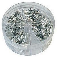
KIT FERRULE NONINS AWG22-14
Manufacturer
Panduit Corp
Series
Pan-Term®r
Type
Ferrule kitr
Datasheet
1.KP-FSD1.pdf
(1040 pages)
Specifications of KP-F1
Kit Type
Ferrule - Wire End
Values
370 pcs - Assorted Non-Insulated 22 ~ 14 AWG Ferrules
Kit Contents
500 Pieces Of F75-6, 400 Pieces Of F76-6 & F77-6, 300 Pieces Of F78-7, 200 Pieces Of F80-7
Lead Free Status / Rohs Status
Lead free / RoHS Compliant


Management
Identification
Accessories
Connectors
Connectors
& Write-On
Protection
Grounding
Pre-Printed
Cable Ties
Terminals
Permanent
Solutions
Overview
Steel Ties
Lockout/
& Safety
D2.162
Stainless
Raceway
Abrasion
Labeling
Systems
Markers
Tagout
System
Surface
Wiring
Power
Labels
Index
Cable
Cable
Duct
E5.
B1.
B2.
B3.
C1.
C2.
C3.
C4.
D1.
D2.
D3.
E1.
E2.
E3.
E4.
A.
F.
Common Conductor Sizes and Strandings Reference Chart
This chart details the different conductors commonly used in the industry.
For each size, either AWG or Metric, various stranding options are listed.
Typically the higher stranding is used in applications requiring greater
conductor flexibility.
*Strandings required for UL and CSA Certification testing.
AWG
Conductor
26
24
22
20
18
Metric
mm
0.25
0.38
.05
.06
.75
.5
2
No.
128
194
100
*10
*16
25
41
10
19
41
10
19
65
32
14
16
26
19
48
12
21
16
41
26
*7
19
24
65
41
*7
19
1
7
1
7
1
7
7
7
1
1
7
1
1
Individual Strands
mm
1.00
1.02
.05
.05
.13
.41
.16
.10
.08
.16
.51
.20
.13
.07
.05
.10
.16
.64
.16
.13
.25
.16
.10
.05
.07
.27
.21
.16
.30
.20
.80
.25
.81
.13
.16
.32
.20
.37
.20
.25
.13
.16
.40
.25
Diameter
.002
.002
.005
.016
.006
.004
.003
.006
.020
.008
.005
.003
.002
.004
.006
.025
.006
.005
.010
.006
.004
.002
.003
.011
.008
.006
.012
.008
.031
.010
.032
.005
.006
.013
.008
.015
.008
.039
.010
.040
.005
.006
.016
.010
In.
Overall Conductor Size
mm
1.10
1.20
1.00
1.19
1.02
1.19
1.19
1.22
1.24
.25
.36
.53
.41
.48
.51
.58
.58
.51
.61
.61
.65
.65
.65
.65
.64
.76
.76
.76
.79
.80
.80
.80
.80
.80
.80
.90
.90
.80
.89
.81
.91
.97
.94
91
Diameter
0.047
.010
.014
.021
.016
.019
.020
.023
.023
.020
.024
.024
.026
.026
.026
.026
.025
.030
.030
.030
.031
.031
.031
.031
.031
.031
.031
.035
.035
.031
.035
.032
.036
.036
.038
.037
.043
.047
.039
.040
.047
.047
.048
.049
In.
ELECTRICAL SOLUTIONS
MILS
Area
Circ.
1000
1024
1025
1032
1111
1216
1485
1488
1550
1600
1600
1625
1627
1770
1900
159
250
256
278
304
384
397
400
448
475
484
496
496
556
625
635
650
700
754
744
752
760
791
820
833
977
992
992
97
AWG
Conductor
16
14
12
10
Metric
mm
1.0
1.5
2.5
4.0
6.0
2
*105
No.
105
189
315
165
511
756
*26
*41
*65
19
32
19
65
30
21
45
19
50
35
19
56
19
37
49
84
19
*7
*7
*7
*7
1
7
1
7
1
1
7
1
1
1
1
1
7
Individual Strands
mm
0.25
1.13
1.30
1.38
1.63
1.78
2.06
2.26
2.59
2.76
1.05
.20
.43
.29
.16
.25
.13
.51
.25
.30
.10
.52
.16
.38
.25
.64
.25
.67
.30
.10
.45
.25
.16
.81
.30
.10
.52
.40
.36
.98
.25
.30
.10
.64
Diameter
.010
.044
.008
.017
.011
.006
.010
.051
.005
.020
.010
.012
.004
.020
.054
.006
.014
.064
.010
.025
.010
.026
.012
.004
.070
.018
.010
.006
.081
.032
.012
.089
.004
.020
.016
.014
.039
.102
.010
.012
.004
.109
.041
.025
In.
AWG to Metric Wire Crosses
AWG
26 – 22
22 – 18
16 – 14
12 – 10
Overall Conductor Size
mm
1.30
1.13
1.30
1.30
1.47
1.50
1.50
1.30
1.50
1.52
1.70
1.60
1.90
1.60
1.38
1.85
1.85
1.63
1.85
1.85
2.20
2.10
2.20
2.20
1.78
2.36
2.41
2.41
2.06
2.44
3.10
2.26
3.00
2.70
2.92
2.95
2.95
2.59
2.95
3.50
3.70
2.76
3.20
3.30
Diameter
Metric (mm²)
.051
.044
.051
.051
.058
.059
.059
.051
.059
.060
.067
.063
.075
.063
.054
.073
.073
.064
.073
.073
.087
.083
.087
.087
.070
.093
.095
.095
.081
.096
.122
.089
.118
.106
.115
.116
.116
.102
.116
.138
.146
.109
.126
.130
In.
0.1 – 0.5
0.5 – 1.0
1.5 – 2.5
4.0 – 6.0
MILS
10376
10404
10500
11718
11718
11807
11962
12063
Area
Circ.
1841
1979
1984
2006
2426
2580
2600
2601
2625
2828
2906
2930
2930
2934
2952
3786
3831
4096
4100
4481
4844
4871
4883
4883
4911
6088
6500
6549
6561
7168
7812
7917
7921
7963
9354
9880