KP-F1 Panduit Corp, KP-F1 Datasheet - Page 263
KP-F1
Manufacturer Part Number
KP-F1
Description
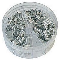
KIT FERRULE NONINS AWG22-14
Manufacturer
Panduit Corp
Series
Pan-Term®r
Type
Ferrule kitr
Datasheet
1.KP-FSD1.pdf
(1040 pages)
Specifications of KP-F1
Kit Type
Ferrule - Wire End
Values
370 pcs - Assorted Non-Insulated 22 ~ 14 AWG Ferrules
Kit Contents
500 Pieces Of F75-6, 400 Pieces Of F76-6 & F77-6, 300 Pieces Of F78-7, 200 Pieces Of F80-7
Lead Free Status / Rohs Status
Lead free / RoHS Compliant


• Material: Halogen-free modified polyphenylene oxide (mPPO)
• UL recognized continuous use temperature: 203°F (95°C)
• UL 94 flammability rating of V-0
• NNC solid divider wall can be mounted inside NNC and NE wiring
• Material: Halogen-free modified polyphenylene oxide (mPPO)
Panduct
material as verified with IEC 60754-2 test method (test on gases
evolved during combustion of electric cables)
duct to create multiple channels
Multiple slot restrictors present with
75mm and greater duct wall height.
H
.39 TYP [10.0]
®
Type NNC Divider Wall
W
.98 TYP [25.0]
Panduct
®
Type NNC Halogen-Free Metric Wiring Duct
Available in LG (Light Gray) and WH (White).
Do not allow cutting, tapping, or cleaning fluids that contain hydrocarbons to come in contact with type NNC
wiring duct as it will cause stress cracking. See page C1.49 for a list of chemicals to avoid.
*"H" dimension includes duct and cover.
Available in WH (White) color only.
NOTE: Must be used with mounting base DB-C (see page C1.26), which is sold separately. Install mounting bases
to the duct channel, locate within 2" of each divider wall end and at least every 12" along the length.
Base and Cover
Part Number
NNC25X25LG2
NNC25X37LG2
NNC25X50LG2
NNC25X75LG2
NNC37X37LG2
NNC37X50LG2
NNC37X75LG2
NNC50X50LG2
NNC50X75LG2
NNC50X100LG2
NNC75X75LG2
NNC100X50LG2
NNC100X75LG2
NNC100X100LG2
Part Number
NNC50DWH2
NNC75DWH2
For technical assistance in the U.S., call 866-405-6654 (outside the U.S., see inside back cover for directory)
ELECTRICAL SOLUTIONS
24.6 x 23.6
24.6 x 35.8
24.6 x 47.8
24.6 x 72.4
37.1 x 35.8
37.1 x 47.8
37.1 x 72.4
49.5 x 47.8
49.5 x 72.4
49.5 x 97.8
74.7 x 72.4
99.6 x 47.8
99.6 x 72.4
99.6 x 97.8
Duct Size (W x H)*
mm
• Conforms with NFPA 79-2007 section 13.3.1 requirement for
• Provided with DIN 43 659 mounting holes
• Metric sizing and finger progression
• Duct and cover packaged together in two meter lengths
Length
• Simply install the divider wall base when mounting the duct
flame retardant material
and snap the divider wall onto mounting base, DB-C
(m)
2
2
1.46 x 1.41
1.46 x 1.88
1.46 x 2.85
1.95 x 1.88
1.95 x 2.85
1.95 x 3.85
2.94 x 2.85
3.92 x 1.88
3.92 x 2.85
3.92 x 3.85
.97 x 1.41
.97 x 1.88
.97 x 2.85
.97 x .93
In.
Slot Width
.39
.39
.39
.39
.39
.39
.39
.39
.39
.39
.39
.39
.39
.39
In.
10.0
10.0
10.0
10.0
10.0
10.0
10.0
10.0
10.0
10.0
10.0
10.0
10.0
10.0
mm
For Nominal
Duct Height
Replacement
Part Number
NC100LG2
NC100LG2
NC100LG2
NC25LG2
NC25LG2
NC25LG2
NC25LG2
NC37LG2
NC37LG2
NC37LG2
NC50LG2
NC50LG2
NC50LG2
NC75LG2
(mm)
Cover
50
75
Cover
Base
Ctn.
Qty.
and
(m)
20
20
20
20
20
20
20
20
10
10
10
10
10
10
Replacement
Pkg.
Std.
Qty.
2
2
Cover
Ctn.
Qty.
(m)
20
20
20
20
20
20
20
20
20
20
20
20
20
20
Ctn.
Std.
Qty.
(m)
40
40
C1.23
Management
Identification
Accessories
Connectors
Connectors
Grounding
Pre-Printed
& Write-On
Protection
Permanent
Solutions
Cable Ties
Terminals
Lockout/
Overview
Steel Ties
& Safety
Stainless
Raceway
Abrasion
Labeling
Systems
Surface
Markers
Tagout
System
Wiring
Labels
Power
Cable
Cable
Index
Duct
E5.
B1.
B2.
B3.
D1.
D2.
D3.
C1.
C2.
C3.
C4.
E1.
E2.
E3.
E4.
A.
F.