KP-F1 Panduit Corp, KP-F1 Datasheet - Page 585
KP-F1
Manufacturer Part Number
KP-F1
Description
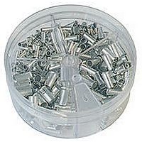
KIT FERRULE NONINS AWG22-14
Manufacturer
Panduit Corp
Series
Pan-Term®r
Type
Ferrule kitr
Datasheet
1.KP-FSD1.pdf
(1040 pages)
Specifications of KP-F1
Kit Type
Ferrule - Wire End
Values
370 pcs - Assorted Non-Insulated 22 ~ 14 AWG Ferrules
Kit Contents
500 Pieces Of F75-6, 400 Pieces Of F76-6 & F77-6, 300 Pieces Of F78-7, 200 Pieces Of F80-7
Lead Free Status / Rohs Status
Lead free / RoHS Compliant


For applicator information, see page D1.143.
For applicator information, see page D1.143.
Type PV-SLFB
Type PN-FF
• Continuously molded design provides reliable, consistent
• Flange design provides extra secure connection on a variety
• Fork design provides for fast and easy installation, without the
• Continuously molded design provides reliable, consistent
• Lock in place for a secure connection in limited spaces
• Fork design provides for fast and easy installation, without the
Part Number
PN18-6FF-3K
PN18-8FF-3K
PN18-10FF-3K
PN14-6FF-3K
PN14-8FF-3K
PN14-10FF-3K
PN10-8FF-2K
PN10-10FF-2K
Part Number
PV18-5SLFB-3K
PV18-6SLFB-3K
PV18-8SLFB-3K
PV18-10SLFB-3K
PV14-6SLFB-3K
PV14-8SLFB-3K
PV14-10SLFB-3K
PV14-14SLFB-3K
PV10-6SLFB-2K
PV10-8SLFB-2K
PV10-10SLFB-2K
performance through the applicator for a high quality termination
every time
need to remove fastener
performance through the applicator for a high quality termination
every time
of applications
need to remove fastener
Flanged Fork Terminals, Nylon Insulated – Non-Funnel Entry
Short Locking Fork Terminals, Vinyl Insulated – Funnel Entry
22 – 18
16 – 14
12 – 10
22 – 18
16 – 14
12 – 10
Range
Range
AWG
AWG
AWG
AWG
AWG
AWG
Wire
Wire
Yellow
Yellow
Color
Color
Code
Code
Blue
Blue
Red
Red
Thickness
Thickness
For technical assistance in the U.S., call 866-405-6654 (outside the U.S., see inside back cover for directory)
Stock
Stock
0.03
0.03
0.04
(In.)
0.03
0.03
0.04
(In.)
0.136
0.162
0.225
0.150
0.170
0.225
Max.
Max.
(In.)
(In.)
Ins.
Ins.
ELECTRICAL SOLUTIONS
Stud
Stud
Size
Size
1/4"
#10
#10
#10
#10
#10
#10
#6
#8
#6
#8
#8
#5
#6
#8
#6
#8
#6
#8
• Insulation support helps to prevent wire damage in
• UL Flammability UL 94V-0, maximum insulation temperature
• UL and CSA rated up to 600 V per UL 486A/B
• Metal insulation grip sleeve crimps to wire insulation, providing
• Internal barrel serrations assure good wire contact and maximum
• UL Flammability UL 94V-2/HB, maximum insulation temperature
• UL and CSA rated up to 600 V per UL 486A/B
bending applications
221°F (105°C)
protection to the crimp joint during high vibration applications
tensile strength
221°F (105°C)
0.80
0.87
0.87
0.80
0.87
0.87
1.05
1.05
0.72
0.72
0.77
0.78
0.75
0.80
0.81
0.90
0.84
0.90
0.91
L
L
Figure Dimensions
Figure Dimensions
C
C
L
L
0.28
0.31
0.35
0.28
0.31
0.35
0.38
0.38
(In.)
0.26
0.27
0.29
0.33
0.25
0.29
0.33
0.44
0.25
0.29
0.33
(In.)
W
W
0.19
0.19
0.23
0.23
0.19
0.23
0.23
0.29
0.17
0.22
0.22
0.19
0.23
0.23
0.19
0.23
0.23
0.22
0.22
C
C
W
W
Crimp Die
Crimp Die
CD9-1A
CD9-2A
CD9-3B
CD9-1A
CD9-2A
CD9-3B
Series
Series
CA9
CA9
CA-800/EZ
CA-800/EZ
Crimp Die
Crimp Die
CD-800-1
CD-800-2
CD-800-3
CD-800-1
CD-800-2
CD-800-3
Series
Series
Pieces
Pieces
3000
3000
3000
3000
3000
3000
3000
3000
2000
2000
2000
Reel
3000
3000
3000
3000
3000
3000
2000
2000
Reel
Per
Per
D1.113
Management
Identification
Accessories
Connectors
Connectors
Grounding
Pre-Printed
& Write-On
Protection
Permanent
Solutions
Cable Ties
Terminals
Lockout/
Overview
Steel Ties
& Safety
Stainless
Raceway
Abrasion
Labeling
Systems
Surface
Markers
Tagout
System
Wiring
Labels
Power
Cable
Cable
Index
Duct
E5.
B1.
B2.
B3.
D1.
D2.
D3.
C1.
C2.
C3.
C4.
E1.
E2.
E3.
E4.
A.
F.