KP-F1 Panduit Corp, KP-F1 Datasheet - Page 286
KP-F1
Manufacturer Part Number
KP-F1
Description
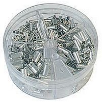
KIT FERRULE NONINS AWG22-14
Manufacturer
Panduit Corp
Series
Pan-Term®r
Type
Ferrule kitr
Datasheet
1.KP-FSD1.pdf
(1040 pages)
Specifications of KP-F1
Kit Type
Ferrule - Wire End
Values
370 pcs - Assorted Non-Insulated 22 ~ 14 AWG Ferrules
Kit Contents
500 Pieces Of F75-6, 400 Pieces Of F76-6 & F77-6, 300 Pieces Of F78-7, 200 Pieces Of F80-7
Lead Free Status / Rohs Status
Lead free / RoHS Compliant


Management
Identification
Accessories
Connectors
Connectors
& Write-On
Protection
Grounding
Pre-Printed
Cable Ties
Terminals
Permanent
Solutions
Overview
Steel Ties
Lockout/
& Safety
Stainless
Raceway
Abrasion
Labeling
Systems
Markers
Tagout
System
Surface
Wiring
Power
Labels
Index
Cable
Cable
Duct
C1.46
E5.
B1.
B2.
B3.
C1.
C2.
C3.
C4.
D1.
D2.
D3.
E1.
E2.
E3.
E4.
A.
F.
General Formula
Panduit Wiring Duct wirefills are calculated using the following general formula:
Why use a 50% Wirefill?
As specified in NFPA79-2007 section 13.5.2, Percentage Fills of Raceways (Ducts), a 50% wirefill is given as
the maximum wirefill capacity in all Panduit Wiring Ducts. This helps ensure general safe wiring practices
are followed. In actual practice, a 50% wirefill is the maximum amount of wiring the duct can hold given the
additional airspace created between cables by non-uniform cable shapes, cable interlacing, and cable
packing factors.
What is the Usable Duct Area?
The usable area we define as the calculation of internal area that can be occupied by wires or cables.
Considering these factors, the usable duct area is equal to an average of 90% of the nominal area,
or (W x H) x .90.
Wire Area
The wire area formula is converted to allow calculation using the cable diameter:
Formula Derivation
Inserting the elements from above into the
general formula results in the following:
Note: When calculating wirefill capacity using the above formula, variables W, H, and D must be expressed in
same units (i.e. mm or inches).
Wirefill Formula
1 This calculation does not account for additional airspace created between cables by non-uniform cable shapes, cable interlacing, and cable packing factors.
2 The resulting formula is used for all Panduit flush cover ducts, this excludes type NE duct which has a different profile design that results in a
divisor of 2.0 x D
corner wiring duct which uses calculated internal area and a divisor of 2.0 x D
Calculation of Internal Area
2
(rather than 1.75 x D
Since we use the outer
channel dimensions in
our calculation, we
make an adjustment in
our formula for the
thickness of material
and for design elements
that extend inside
the channel.
2
as shown here) and type H and HS wiring duct with a profile design that results in a divisor of 1.85 x D
E L E C T R I C A L S O LU T I O N S
Simplifying this formula results in the formula
used for wirefill calculation
2
.
Air Space Allotment
(Note 2):
In our wirefill formula an
adjustment is made to the
channel internal area to
account for “unusable” air
space that will be present
between cables when placed
in the channel. Our formula
assumes a uniform close
packed or high-density
cable arrangement
(see diagram) (Note 1).
2
and