KP-F1 Panduit Corp, KP-F1 Datasheet - Page 63
KP-F1
Manufacturer Part Number
KP-F1
Description
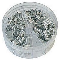
KIT FERRULE NONINS AWG22-14
Manufacturer
Panduit Corp
Series
Pan-Term®r
Type
Ferrule kitr
Datasheet
1.KP-FSD1.pdf
(1040 pages)
Specifications of KP-F1
Kit Type
Ferrule - Wire End
Values
370 pcs - Assorted Non-Insulated 22 ~ 14 AWG Ferrules
Kit Contents
500 Pieces Of F75-6, 400 Pieces Of F76-6 & F77-6, 300 Pieces Of F78-7, 200 Pieces Of F80-7
Lead Free Status / Rohs Status
Lead free / RoHS Compliant


• Natural nylon material for indoor use
• Weather resistant material has greater resistance to damage
• Heat stabilized material for high temperature applications
• Wingless design allows tie to be used in confined spaces
Nylon 6.6
Intermediate Cross Section
Standard Cross Section
Weather Resistant Nylon 6.6
Intermediate Cross Section
Standard Cross Section
Heat Stabilized Nylon 6.6
Intermediate Cross Section
Standard Cross Section
Part Number
PLP1.5I-C
PLP1S-M
PLP1.5S-M
PLP2S-C
PLP1.5I-M0
PLP1S-M0
PLP2S-M0
PLP1.5I-M30
PLP1S-M30
PLP2S-M30
caused by ultraviolet light – indoor or outdoor use
up to 239°F (115°C) – indoor use
PLP2S-C
Pan-Ty
6.1
5.3
6.7
7.9
In.
6.1
5.3
7.9
6.1
5.3
7.9
Length
mm
156
135
170
200
156
135
200
156
135
200
PLP2S-M0
®
Push Mount Ties
.135
.180
.180
.180
.135
.180
.180
.135
.180
.180
In.
Width
mm
3.4
4.6
4.6
4.6
3.4
4.6
4.6
3.4
4.6
4.6
For technical assistance in the U.S., call 866-405-6654 (outside the U.S., see inside back cover for directory)
Thickness
.045
.050
.050
.050
.045
.050
.050
.045
.050
.050
In.
mm
1.1
1.3
1.3
1.3
1.1
1.3
1.3
1.1
1.3
1.3
.187
.250
.250
.250
.187
.250
.250
.187
.250
.250
ELECTRICAL SOLUTIONS
In.
Nominal
Hole
Dia.
mm
4.7
6.4
6.4
6.4
4.7
6.4
6.4
4.7
6.4
6.4
Thickness
.093
.125
.125
.125
.093
.125
.125
.093
.125
.125
In.
• Cable tie, mount, and fastener in a single part
• Economical push mount ties are used to attach bundles to another
• Anchor is easily pressed into a pre-formed hole and locks in place
• Curved tip is easy to pick up from flat surfaces and allows faster
Panel
Max.
surface such as a flat panel
initial threading to speed installation
mm
2.4
3.2
3.2
3.2
2.4
3.2
3.2
2.4
3.2
3.2
1.25
1.00
1.50
1.75
1.25
1.00
1.75
1.25
1.00
1.75
In.
Bundle
Max.
Dia.
mm Lbs.
32
25
38
45
32
25
45
32
25
45
Head Design
Tensile Str.
40
50
50
50
40
50
50
40
50
50
PLP1.5I
Loop
Min.
178
222
222
222
178
222
222
178
222
222
N
Recommended
PPTS, STS2
STS2, STH2
GTS, GTSL,
GTS, GTSL,
GS2B, GTH,
GS4H, PTS,
PPTS, STS2
GS2B, GTH,
STS2, STH2
PPTS, STS2
GS2B, GTH,
STS2, STH2
GS2B, PTS,
PTH, PPTS,
GTS, GTSL,
GS2B, PTS,
GTS, GTSL,
GS4H, PTS,
PTH, PPTS,
GTS, GTSL,
GS2B, PTS,
GTS, GTSL,
GS4H, PTS,
PTH, PPTS,
Installation
Tool
1000 10000
1000 10000
Pkg.
1000 25000
1000 10000
1000 10000
1000 25000
1000 10000
1000 10000
Std.
Qty.
100
100
1000
1000
Std.
Ctn.
Qty.
B1.33
Management
Identification
Accessories
Connectors
Connectors
Grounding
Pre-Printed
& Write-On
Protection
Permanent
Solutions
Cable Ties
Terminals
Lockout/
Overview
Steel Ties
& Safety
Stainless
Raceway
Abrasion
Labeling
Systems
Surface
Markers
Tagout
System
Wiring
Labels
Power
Cable
Cable
Index
Duct
E5.
B1.
B2.
B3.
D1.
D2.
D3.
C1.
C2.
C3.
C4.
E1.
E2.
E3.
E4.
A.
F.