MCP215X/40EV-DB Microchip Technology, MCP215X/40EV-DB Datasheet - Page 22
MCP215X/40EV-DB
Manufacturer Part Number
MCP215X/40EV-DB
Description
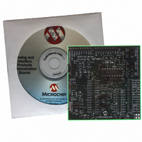
BOARD DEMO FOR MCP215X/40
Manufacturer
Microchip Technology
Datasheet
1.MCP215X40EV-DB.pdf
(94 pages)
Specifications of MCP215X/40EV-DB
Main Purpose
Interface, IrDA
Embedded
Yes, MCU, 8-Bit
Utilized Ic / Part
MCP2150, MCP2155, MCP2140
Primary Attributes
PICDEM™ Demo Board Interface
Processor To Be Evaluated
MCP21x
Interface Type
UART
Lead Free Status / RoHS Status
Contains lead / RoHS non-compliant
Secondary Attributes
-
Lead Free Status / RoHS Status
Lead free / RoHS Compliant, Contains lead / RoHS non-compliant
Available stocks
Company
Part Number
Manufacturer
Quantity
Price
Company:

Part Number:
MCP215X/40EV-DB
Manufacturer:
MICROCHIP
Quantity:
12 000


DS51591A-page 18
Figure 2-4 shows the component layout for the MCP215X/40 Developer’s Daughter
Board and the operation of the JMP1, JMP2, JMP3, JMP4, JP8 and JP9 jumpers.
The JMP1, JMP2, JMP3 and JMP4 jumpers route signals to the U1 socket (for the
MCP215X or MCP2140 device).
Table 2-2 shows the signals for the JMP1, JMP2 and JMP3 jumpers, while Table 2-3
shows the signals for the JMP4 jumper.
TABLE 2-2:
TABLE 2-3:
JMP1
JMP2
JMP3
JMP4
Note 1:
Jumper
Jumper
1
18
3
10 or 17
connection to
connection to
See Appendix J. “PCB Silk-Screen Clarification” for a clarification to the PCB
silk-screen.
(Center pin)
(Center pin)
JMPX-2 pin
JMPX-2 pin
U1 pin
U1 pin
JMP1, JMP2 AND JMP3 CONNECTIONS
JMP4 CONNECTIONS
BAUD0
BAUD1
RXIR
U1-17 (CD)
MCP215X
MCP2150
(DTE)
RXPD
PHACT
(DSR)
RXPDREF
U1-10
MCP2140
MCP2155
MCP2140
(1)
(DCE)
and
The center tap of the JMP4 jumper
drives the “IR Link” LED. This
indicates that an IR Link is
established.
© 2006 Microchip Technology Inc.
Comment
Comment
Related parts for MCP215X/40EV-DB
Image
Part Number
Description
Manufacturer
Datasheet
Request
R

Part Number:
Description:
Manufacturer:
Microchip Technology Inc.
Datasheet:
Part Number:
Description:
Manufacturer:
Microchip Technology Inc.
Datasheet:
Part Number:
Description:
Manufacturer:
Microchip Technology Inc.
Datasheet:
Part Number:
Description:
Manufacturer:
Microchip Technology Inc.
Datasheet:
Part Number:
Description:
Manufacturer:
Microchip Technology Inc.
Datasheet:
Part Number:
Description:
Manufacturer:
Microchip Technology Inc.
Datasheet:
Part Number:
Description:
Manufacturer:
Microchip Technology Inc.
Datasheet:
Part Number:
Description:
Manufacturer:
Microchip Technology Inc.
Datasheet: