MCP215X/40EV-DB Microchip Technology, MCP215X/40EV-DB Datasheet - Page 25
MCP215X/40EV-DB
Manufacturer Part Number
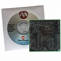
MCP215X/40EV-DB
Description
BOARD DEMO FOR MCP215X/40
Manufacturer
Microchip Technology
Datasheet
1.MCP215X40EV-DB.pdf
(94 pages)
Specifications of MCP215X/40EV-DB
Main Purpose
Interface, IrDA
Embedded
Yes, MCU, 8-Bit
Utilized Ic / Part
MCP2150, MCP2155, MCP2140
Primary Attributes
PICDEM™ Demo Board Interface
Processor To Be Evaluated
MCP21x
Interface Type
UART
Lead Free Status / RoHS Status
Contains lead / RoHS non-compliant
Secondary Attributes
-
Lead Free Status / RoHS Status
Lead free / RoHS Compliant, Contains lead / RoHS non-compliant
Available stocks
Company
Part Number
Manufacturer
Quantity
Price
Company:

Part Number:
MCP215X/40EV-DB
Manufacturer:
MICROCHIP
Quantity:
12 000


2.4
TABLE 2-5:
© 2006 Microchip Technology Inc.
Note 1:
Qty
1
1
1
1
1
1
1
PC with:
IR port
and USB/Serial port to IR Dongle
and
One serial port to communicate to the
PICDEM HPC Explorer Demo Board.
Serial Cable
MCP215X/40 Developer’s Daughter
Board
PICDEM™ HPC Explorer Board or
PICDEM™ FS USB Board
PICDEM™ HPC Explorer Demo Board
Power Supplies (9V DC)
MPLAB ICD2 Hardware
MPLAB IDE Software
MAKING A DEMO SYSTEM
This could be done with one or two PCs, depending on the features of the selected PC.
(1)
or PC with USB/Serial port
SYSTEM HARDWARE REQUIREMENTS
Hardware
The MCP215X/40 Developer’s Daughter Board requires a Host Controller or a UART
circuit. To demonstrate the board, the easiest method is to use one of the compatible
PICDEM™ Demo Boards. A good choice is the PICDEM™ HPC Explorer Demo Board.
This allows the MCP215X or MCP2140 device to interface to either:
• PIC18F8722’s EUSART1
• PIC18F8722’s EUSART2
• PICDEM™ HPC Explorer Demo Board’s DB-9 connector (MAX3232C)
Additional instructions for performing a demo using the PICDEM™ HPC Explorer
Demo Board are shown in Appendix D. “Using the MCP215X/40 Developer’s
Daughter Board with the PICDEM™ HPC Explorer Demo Board”. Appendix
E. “Using the MCP215X/40 Developer’s Daughter Board with the PICDEM™ FS
USB Demo Board” supplies instructions for performing a demo using the PICDEM™
FS USB Demo Board. Appendix F. “Configuring the HyperTerminal
may be useful for configuring the HyperTerminal program on the PC.
System Requirements
Table 2-5 shows the requirements for a system that can be used to demonstrate the
MCP215X/40 Developer’s Daughter Board.
System Setup
The system setup requires a Primary Device and a Secondary Device. The Primary
Device can be a PC with an IR port (integrated IR port or IR Dongle) or a PDA. The
secondary device can be the embedded system (PICDEM™ HPC Explorer Demo
Board and a MCP215X/40 Developer’s Daughter Board) in a stand-alone mode or con-
nected to a PC with a serial communication port (UART) and application program, such
as HyperTerminal.
Figure 2-5 shows a system block diagram.
(1)
Purpose
As a Primary Device, this device will initiate communication to the
MCP215X/40 Developer’s Daughter Board.
Also
For Demo#3, the PC will also “talk” to the PICDEM™ HPC Explorer
Demo Board (Encoder/Decoder board) via the serial port and a
session of the HyperTerminal
To connect the PC serial ports to the PICDEM™ HPC Explorer Demo
Board’s serial port.
This board being demonstrated.
The MCP215X/40 Developer’s Daughter Board will be installed into
this board for demonstrated.
Used to power the PICDEM™ HPC Explorer Demo Boards. Pro-
grammed with the 00077 - HPC.asm code.
Allows you to program the PICmicro MCUs on either the PICDEM™
HPC Explorer Board or PICDEM™ FS USB Board.
The Integrated Development Environment for developing PICmicro
MCU programs and the programming the devices.
®
program.
DS51591A-page 21
®
Program”
Related parts for MCP215X/40EV-DB
Image
Part Number
Description
Manufacturer
Datasheet
Request
R

Part Number:
Description:
Manufacturer:
Microchip Technology Inc.
Datasheet:
Part Number:
Description:
Manufacturer:
Microchip Technology Inc.
Datasheet:
Part Number:
Description:
Manufacturer:
Microchip Technology Inc.
Datasheet:
Part Number:
Description:
Manufacturer:
Microchip Technology Inc.
Datasheet:
Part Number:
Description:
Manufacturer:
Microchip Technology Inc.
Datasheet:
Part Number:
Description:
Manufacturer:
Microchip Technology Inc.
Datasheet:
Part Number:
Description:
Manufacturer:
Microchip Technology Inc.
Datasheet:
Part Number:
Description:
Manufacturer:
Microchip Technology Inc.
Datasheet: