MCP215X/40EV-DB Microchip Technology, MCP215X/40EV-DB Datasheet - Page 24
MCP215X/40EV-DB
Manufacturer Part Number
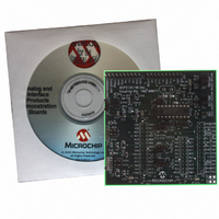
MCP215X/40EV-DB
Description
BOARD DEMO FOR MCP215X/40
Manufacturer
Microchip Technology
Datasheet
1.MCP215X40EV-DB.pdf
(94 pages)
Specifications of MCP215X/40EV-DB
Main Purpose
Interface, IrDA
Embedded
Yes, MCU, 8-Bit
Utilized Ic / Part
MCP2150, MCP2155, MCP2140
Primary Attributes
PICDEM™ Demo Board Interface
Processor To Be Evaluated
MCP21x
Interface Type
UART
Lead Free Status / RoHS Status
Contains lead / RoHS non-compliant
Secondary Attributes
-
Lead Free Status / RoHS Status
Lead free / RoHS Compliant, Contains lead / RoHS non-compliant
Available stocks
Company
Part Number
Manufacturer
Quantity
Price
Company:

Part Number:
MCP215X/40EV-DB
Manufacturer:
MICROCHIP
Quantity:
12 000


TABLE 2-4:
DS51591A-page 20
JP1C:JP2C Connects TXIR/RXIR signals to TXD/RXD of U5 (TFDU 4300)
Legend: S = Jumper is shorted (Closed)
Note 1: The MCP2140’s RX signal is either connected via JMP5 or JP6 (but not both at the same time).
JP1A:JP2A Connects TXIR/RXIR signals to TXD/RXD of U2 (HSDL 3000)
JP1B:JP2B Connects TXIR/RXIR signals to TXD/RXD of U3 (TFDU 4100)
Jumper #
JP2:JP1
JP4:JP3
JMP1
JMP2
JMP3
JMP4
JMP5
JMP6
JP5
JP6
JP7
JP8
JP9
2: The MCP2140’s TX signal is either connected via JMP6 or JP7 (but not both at the same time).
S = TXIR/RXIR connected to U2 TXD/RXD
O = TXIR/RXIR Not connected to U2 TXD/RXD
S = TXIR/RXIR connected to U3 TXD/RXD
O = TXIR/RXIR Not connected to U3 TXD/RXD
S = TXIR/RXIR connected to U5 TXD/RXD
O = TXIR/RXIR Not connected to U5 TXD/RXD
BAUD1:BAUD0 Hardware control of the MCP215X baud rate.
BAUD0 is connected to Header RA0 signal and BAUD1 is
connected to Header RA0 signal
S S = 9600 Baud
S O = 19200 Baud
O S = 57600 Baud
O O = 115200 Baud
MODE1:MODE0 Hardware program mode selection. Operation
is dependant on the Host Controller program.
00077 - HPC.asm Operation
S S = Direct-to-PC
S O = Reserved
O S = Data Echo
O O = Data Logger (250 Byte data transfer)
EN Hardware control of the MCP215X EN signal.
EN is connected to Header RA0 signal.
S = Signal Connected to V
O = Signal Connected to V
Connects the U1 pin 1 to either the BAUD0 signal (MCP215X)
or to the RXPDREF signal (MCP2140).
Connects the U1 pin 18 to either the BAUD1 signal (MCP215X)
or to the RXPD signal (MCP2140).
Connects the U1 pin 3 to either the RXIR signal (MCP215X) or
to the PHACT signal (MCP2140).
Connects the “IR Link” signal to either the U1-17 signal (CD) for
the MCP2150 device or to the U1-10 signal (DSR) for the
MCP2155 or MCP2140 device.
Connects MCP2140 RX signal to either Header 1’s RX signal or
Header 2/Header 3 RX signals
Connects MCP2140 RX signal to Header 1’s TX signal
Connects MCP2140 TX signal to Header 1’s TX
signal or Header 2/Header 3 TX signals
Connects MCP2140 TX signal to Header 1’s RX
signal
Connects the RX2 signal (H3-9) to the H3-8 pin (RX2B)
Connects the TX2 signal (H3-11) to the H3-10 pin (TX2B)
JUMPER DESCRIPTIONS AND SETTINGS
Description
SS
DD
O = Jumper is Open
By default not installed.
By default not installed.
By default not installed. PCB traces
short these jumpers (bottom of PCB).
S = Signal Connected to V
O = Signal Connected to V
The MCP2140 has a fixed baud rate
of 9600 baud.
S = Signal Connected to V
O = Signal Connected to V
These operational modes are for the
00077 - HPC.asm program with the
PICDEM™ HPC Explorer Board.
The MCP2140 does not use this
signal.
Note 1
Used when the MCP215X or
MCP2140 communicates directly from
the DB-9 connector. (Note 1)
Note 2
Used when the MCP215X or
MCP2140 communicates directly from
the DB-9 connector. (Note 2)
For PICDEM™ 2 Plus Support.
For PICDEM™ 2 Plus Support.
© 2006 Microchip Technology Inc.
Comment
SS
SS
DD
DD
Related parts for MCP215X/40EV-DB
Image
Part Number
Description
Manufacturer
Datasheet
Request
R

Part Number:
Description:
Manufacturer:
Microchip Technology Inc.
Datasheet:
Part Number:
Description:
Manufacturer:
Microchip Technology Inc.
Datasheet:
Part Number:
Description:
Manufacturer:
Microchip Technology Inc.
Datasheet:
Part Number:
Description:
Manufacturer:
Microchip Technology Inc.
Datasheet:
Part Number:
Description:
Manufacturer:
Microchip Technology Inc.
Datasheet:
Part Number:
Description:
Manufacturer:
Microchip Technology Inc.
Datasheet:
Part Number:
Description:
Manufacturer:
Microchip Technology Inc.
Datasheet:
Part Number:
Description:
Manufacturer:
Microchip Technology Inc.
Datasheet: