MCP215X/40EV-DB Microchip Technology, MCP215X/40EV-DB Datasheet - Page 59
MCP215X/40EV-DB
Manufacturer Part Number
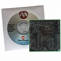
MCP215X/40EV-DB
Description
BOARD DEMO FOR MCP215X/40
Manufacturer
Microchip Technology
Datasheet
1.MCP215X40EV-DB.pdf
(94 pages)
Specifications of MCP215X/40EV-DB
Main Purpose
Interface, IrDA
Embedded
Yes, MCU, 8-Bit
Utilized Ic / Part
MCP2150, MCP2155, MCP2140
Primary Attributes
PICDEM™ Demo Board Interface
Processor To Be Evaluated
MCP21x
Interface Type
UART
Lead Free Status / RoHS Status
Contains lead / RoHS non-compliant
Secondary Attributes
-
Lead Free Status / RoHS Status
Lead free / RoHS Compliant, Contains lead / RoHS non-compliant
Available stocks
Company
Part Number
Manufacturer
Quantity
Price
Company:

Part Number:
MCP215X/40EV-DB
Manufacturer:
MICROCHIP
Quantity:
12 000


TABLE D-4:
© 2006 Microchip Technology Inc.
1
2
3
4
5
6
7
8
9
10
11
12
13
Step Action
Place both devices on a flat surface about 25 cm (10”)
apart, and with the IR ports facing each other.
On the System #1 Unit (IR Dongle):
Connect Serial to IR dongle to PC. Ensure that device
supports the IrCOMM 9-wire “cooked” service class.
On the PICDEM™ HPC Explorer Demo Board plus
MCP215X/40 Developer’s Daughter Board:
Insert the MCP215X/40 Developer’s Daughter Board
into the PICDEM HPC Explorer Demo Board.
Ensure that the jumpers are configured as in
Figure D-7.
On the PICDEM HPC Explorer Demo Board plus
MCP215X/40 Developer’s Daughter Board:
Apply power to the unit via the 9V power supply.
On the PICDEM HPC Explorer Demo Board plus
MCP215X/40 Developer’s Daughter Board:
Ensure that the PC serial port (COM1/2) cable is
connected to the PICDEM HPC Explorer Demo Board
DB-9 connector.
On the PICDEM HPC Explorer Demo Board plus
MCP215X/40 Developer’s Daughter Board:
Depress and release the RESET Switch (S2 – MCLR).
On the PC:
“Connect” the HyperTerminal
the Primary Device (such as COM 7). Ensure that the
window indicates that the HyperTerminal program is
connected.
On the PC:
Open the HyperTerminal program window for the Sec-
ondary Device (embedded system) which would be
connected to one on the standard COM ports (such as
COM1).
On the PC:
In the Secondary Device HyperTerminal program win-
dow (COM1), type alpha-numeric characters (such as
“123456 asdfg”).
On the PC:
In the Primary Device HyperTerminal program window
(COM7), depress the Return key and type
alpha-numeric characters (such as “7890 hjkl;”).
Step 9 through Step 10 may be repeated.
On the PC:
“Disconnect” the HyperTerminal program window for
the Secondary Device (embedded system) which
would be connected to one on the standard COM
ports (such as COM1).
On the PC:
“Disconnect” the HyperTerminal program window for
the Primary Device (such as COM 7).
DEMO #3 STEPS
Using the MCP215X/40 Developer’s Daughter Board
®
program window for
with the PICDEM™ HPC Explorer Demo Board
Result
—
—
—
On the PICDEM HPC Explorer Demo Board plus
MCP215X/40 Developer’s Daughter Board:
The green power LED (D) will turn on.
—
—
On the PICDEM HPC Explorer Demo Board plus
MCP215X/40 Developer’s Daughter Board:
The “IR Link” LED will turn on and the “CTS” LED will
strobe rapidly and then return to the normal rate.
—
On the PC:
In the Primary Device HyperTerminal program
window (COM7), the same characters should be
displayed (“123456 asdfg”).
On the PC:
In the Secondary Device HyperTerminal program
window (COM1), the same characters should be
displayed (“7890 hjkl;”) on the line below the “123456
asdfg” characters.
—
—
On the PC:
The IR icon in the system tray will show that the link
has been disconnected.
DS51591A-page 55
Related parts for MCP215X/40EV-DB
Image
Part Number
Description
Manufacturer
Datasheet
Request
R

Part Number:
Description:
Manufacturer:
Microchip Technology Inc.
Datasheet:
Part Number:
Description:
Manufacturer:
Microchip Technology Inc.
Datasheet:
Part Number:
Description:
Manufacturer:
Microchip Technology Inc.
Datasheet:
Part Number:
Description:
Manufacturer:
Microchip Technology Inc.
Datasheet:
Part Number:
Description:
Manufacturer:
Microchip Technology Inc.
Datasheet:
Part Number:
Description:
Manufacturer:
Microchip Technology Inc.
Datasheet:
Part Number:
Description:
Manufacturer:
Microchip Technology Inc.
Datasheet:
Part Number:
Description:
Manufacturer:
Microchip Technology Inc.
Datasheet: