MCP215X/40EV-DB Microchip Technology, MCP215X/40EV-DB Datasheet - Page 32
MCP215X/40EV-DB
Manufacturer Part Number
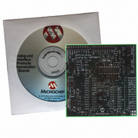
MCP215X/40EV-DB
Description
BOARD DEMO FOR MCP215X/40
Manufacturer
Microchip Technology
Datasheet
1.MCP215X40EV-DB.pdf
(94 pages)
Specifications of MCP215X/40EV-DB
Main Purpose
Interface, IrDA
Embedded
Yes, MCU, 8-Bit
Utilized Ic / Part
MCP2150, MCP2155, MCP2140
Primary Attributes
PICDEM™ Demo Board Interface
Processor To Be Evaluated
MCP21x
Interface Type
UART
Lead Free Status / RoHS Status
Contains lead / RoHS non-compliant
Secondary Attributes
-
Lead Free Status / RoHS Status
Lead free / RoHS Compliant, Contains lead / RoHS non-compliant
Available stocks
Company
Part Number
Manufacturer
Quantity
Price
Company:

Part Number:
MCP215X/40EV-DB
Manufacturer:
MICROCHIP
Quantity:
12 000


DS51591A-page 28
TABLE 2-10:
RXPDREF
TXIR
RXPD
Legend: A = Analog
2.5.2.2.1
In addition to the signals described in Table 2-9 and Table 2-10, there are two additional
signals that can be used by the Host Controller. These are:
1. The RESET signal.
2. The PHACT (Protocol Handler Active) signal.
The MCP2140 RESET pin is connected to an I/O pin of the Host Controller. The H1/H3
headers each have the RESET signal connected to two pins, RA5 and RC3. The Host
Controller determines when the MCP215X device needs to be reset.
The MCP2140 PHACT (Protocol Handler Active) output signal indicates the current
mode the MCP2140 IrDA
or Low-power mode,1 = Discovery or NRM). An LED (D4) can be jumpered to the
MCP2140’s PHACT pin. This is done with jumper JMP3. The PHACT signal is not
connected to the H1/H3 headers.
Pin Name
I = Input
Additional MCP215X Interface Signals
Number
(SSOP)
Pin
20
MCP2140 IR INTERFACE PINS
1
2
Type
Pin
O
®
I
I
standard protocol controller state machine is in (0 = NDM
Buffer
Type
—
A
A
IR Receive Photo Detect Diode reference voltage.
This voltage will typically be in the range of V
Asynchronous transmit to IrDA
transceiver.
IR RX Photo Detect Diode input. This input signal is
required to be a pulse to indicate an IR bit. When
the amplitude of the signal crosses the amplitude
threshold set by the RXPDREF pin, the IR bit is
detected. The pulse has minimum and maximum
requirements as specified in the MCP2140 data
sheet, Electrical Characteristics table,
Parameter IR131A.
P = Power
O = Output
Description
© 2006 Microchip Technology Inc.
®
standard
DD
/2.
Related parts for MCP215X/40EV-DB
Image
Part Number
Description
Manufacturer
Datasheet
Request
R

Part Number:
Description:
Manufacturer:
Microchip Technology Inc.
Datasheet:
Part Number:
Description:
Manufacturer:
Microchip Technology Inc.
Datasheet:
Part Number:
Description:
Manufacturer:
Microchip Technology Inc.
Datasheet:
Part Number:
Description:
Manufacturer:
Microchip Technology Inc.
Datasheet:
Part Number:
Description:
Manufacturer:
Microchip Technology Inc.
Datasheet:
Part Number:
Description:
Manufacturer:
Microchip Technology Inc.
Datasheet:
Part Number:
Description:
Manufacturer:
Microchip Technology Inc.
Datasheet:
Part Number:
Description:
Manufacturer:
Microchip Technology Inc.
Datasheet: