MCP215X/40EV-DB Microchip Technology, MCP215X/40EV-DB Datasheet - Page 31
MCP215X/40EV-DB
Manufacturer Part Number
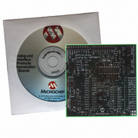
MCP215X/40EV-DB
Description
BOARD DEMO FOR MCP215X/40
Manufacturer
Microchip Technology
Datasheet
1.MCP215X40EV-DB.pdf
(94 pages)
Specifications of MCP215X/40EV-DB
Main Purpose
Interface, IrDA
Embedded
Yes, MCU, 8-Bit
Utilized Ic / Part
MCP2150, MCP2155, MCP2140
Primary Attributes
PICDEM™ Demo Board Interface
Processor To Be Evaluated
MCP21x
Interface Type
UART
Lead Free Status / RoHS Status
Contains lead / RoHS non-compliant
Secondary Attributes
-
Lead Free Status / RoHS Status
Lead free / RoHS Compliant, Contains lead / RoHS non-compliant
Available stocks
Company
Part Number
Manufacturer
Quantity
Price
Company:

Part Number:
MCP215X/40EV-DB
Manufacturer:
MICROCHIP
Quantity:
12 000


© 2006 Microchip Technology Inc.
2.5.2.2
The key signals for the MCP2140-to-microcontroller (Host UART) interface are shown
in Table 2-9. The key signals for the MCP2140-to-IR transceiver circuit are shown in
Table 2-10. Further information on the Host Controller interface may be obtained from
the MCP2140 data sheet, (DS21790).
TABLE 2-9:
TX
RX
RI
DSR
DTR
CTS
RTS
CD
Legend:
Note 1:
Pin Name
TTL = TTL compatible input
I = Input
The state of the DTR output pin does not reflect the state of the DTR bit of the
IrDA
MCP2140 IrDA
Number
(SSOP)
®
Pin
MCP2140 HOST UART INTERFACE PINS
10
12
13
14
19
standard Primary device.
11
8
9
Type
Pin
O
O
O
I
I
I
I
I
®
PROTOCOL STACK CONTROLLER DEVICE
Buffer
Type
TTL
TTL
TTL
TTL
ST
—
—
—
ST = Schmitt Trigger input with CMOS levels
O = Output
Asynchronous receive; from Host Controller UART.
Asynchronous transmit; to Host Controller UART.
Ring Indicator. The state of this bit is
communicated to the IrDA
device.
1 = No Ring Indicate Present.
0 = Ring Indicate Present.
Data Set Ready. Indicates that the MCP2150 has
established a valid infrared link with a Primary
device. This signal is locally emulated and not
related to the DTR bit of the IrDA
Primary device. (Note 1)
1 = An IR link has not been established
0 = An IR link has been established (IR Link).
Data Terminal Ready. Indicates that the embedded
device connected to the MCP2150 is ready for IR
data. The state of this bit is communicated to the
IrDA
bit carried by IrCOMM.
1 = Embedded device not ready.
0 = Embedded device ready.
Clear to Send. Indicates that the MCP2150 is
ready to receive data from the Host Controller. This
signal is locally emulated and not related to the
CTS/RTS bit of the IrDA
1 = Host Controller should not send data.
0 = Host Controller may send data.
Request to Send. Indicates that a Host Controller is
ready to receive data from the MCP2150. This
signal is locally emulated and not related to the
CTS/RTS bit of the IrDA
1 = Host Controller not ready to receive data.
0 = Host Controller ready to receive data.
Carrier Detect. The state of this bit is
communicated to the IrDA
device via the IrDA
1 = No Carrier Present.
0 = Carrier Present.
(No IR Link).
®
Primary device, via the IrDA
®
Description
standard CD bit.
®
®
standard Primary device.
standard Primary device.
®
®
standard Primary
standard Primary
®
DS51591A-page 27
®
standard
standard DSR
Related parts for MCP215X/40EV-DB
Image
Part Number
Description
Manufacturer
Datasheet
Request
R

Part Number:
Description:
Manufacturer:
Microchip Technology Inc.
Datasheet:
Part Number:
Description:
Manufacturer:
Microchip Technology Inc.
Datasheet:
Part Number:
Description:
Manufacturer:
Microchip Technology Inc.
Datasheet:
Part Number:
Description:
Manufacturer:
Microchip Technology Inc.
Datasheet:
Part Number:
Description:
Manufacturer:
Microchip Technology Inc.
Datasheet:
Part Number:
Description:
Manufacturer:
Microchip Technology Inc.
Datasheet:
Part Number:
Description:
Manufacturer:
Microchip Technology Inc.
Datasheet:
Part Number:
Description:
Manufacturer:
Microchip Technology Inc.
Datasheet: