MCP215X/40EV-DB Microchip Technology, MCP215X/40EV-DB Datasheet - Page 74
MCP215X/40EV-DB
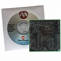
Manufacturer Part Number
MCP215X/40EV-DB
Description
BOARD DEMO FOR MCP215X/40
Manufacturer
Microchip Technology
Datasheet
1.MCP215X40EV-DB.pdf
(94 pages)
Specifications of MCP215X/40EV-DB
Main Purpose
Interface, IrDA
Embedded
Yes, MCU, 8-Bit
Utilized Ic / Part
MCP2150, MCP2155, MCP2140
Primary Attributes
PICDEM™ Demo Board Interface
Processor To Be Evaluated
MCP21x
Interface Type
UART
Lead Free Status / RoHS Status
Contains lead / RoHS non-compliant
Secondary Attributes
-
Lead Free Status / RoHS Status
Lead free / RoHS Compliant, Contains lead / RoHS non-compliant
Available stocks
Company
Part Number
Manufacturer
Quantity
Price
Company:

Part Number:
MCP215X/40EV-DB
Manufacturer:
MICROCHIP
Quantity:
12 000


FIGURE E-4:
DS51591A-page 70
Note 1:
HyperTerminal
Program Window A
(to IrDA
The PC may be a notebook with an integrated IR port.
®
DEMO #2 SYSTEM BLOCK DIAGRAM
E.1.2
In Demo #2, the System #2 unit will echo any alpha character received, changing the
case of the character (lowercase to uppercase/uppercase to lowercase).
The System #1 unit is connected to the PC, while the System #2 unit is not required to
be connected, though it still needs to be powered. The PICDEM FS USB Demo Board
is used to determine the communication baud rate (115,200) via the JP2 and JP1
jumper states. Given this state, the PICmicro MCU can then configure the MCP2150
UART baud rate. Power is supplied over the H1 and H2 interface headers. Jumpers
JP3 and JP4 are used to select which demo program to run. Figure E-5 shows the
jumper configuration for Demo #1.
Table E-3 shows the steps for Demo #2.
Dongle)
®
Demo #2 Operation - Echo Mode
System #1
Serial (UART or USB)
to IrDA Dongle
(1)
(1)
System #2
PICDEM™ FS USB
Demo Board plus
MCP215X/40 Developer’s
Daughter Board
© 2006 Microchip Technology Inc.
Related parts for MCP215X/40EV-DB
Image
Part Number
Description
Manufacturer
Datasheet
Request
R

Part Number:
Description:
Manufacturer:
Microchip Technology Inc.
Datasheet:
Part Number:
Description:
Manufacturer:
Microchip Technology Inc.
Datasheet:
Part Number:
Description:
Manufacturer:
Microchip Technology Inc.
Datasheet:
Part Number:
Description:
Manufacturer:
Microchip Technology Inc.
Datasheet:
Part Number:
Description:
Manufacturer:
Microchip Technology Inc.
Datasheet:
Part Number:
Description:
Manufacturer:
Microchip Technology Inc.
Datasheet:
Part Number:
Description:
Manufacturer:
Microchip Technology Inc.
Datasheet:
Part Number:
Description:
Manufacturer:
Microchip Technology Inc.
Datasheet: