MCP215X/40EV-DB Microchip Technology, MCP215X/40EV-DB Datasheet - Page 64
MCP215X/40EV-DB
Manufacturer Part Number
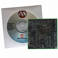
MCP215X/40EV-DB
Description
BOARD DEMO FOR MCP215X/40
Manufacturer
Microchip Technology
Datasheet
1.MCP215X40EV-DB.pdf
(94 pages)
Specifications of MCP215X/40EV-DB
Main Purpose
Interface, IrDA
Embedded
Yes, MCU, 8-Bit
Utilized Ic / Part
MCP2150, MCP2155, MCP2140
Primary Attributes
PICDEM™ Demo Board Interface
Processor To Be Evaluated
MCP21x
Interface Type
UART
Lead Free Status / RoHS Status
Contains lead / RoHS non-compliant
Secondary Attributes
-
Lead Free Status / RoHS Status
Lead free / RoHS Compliant, Contains lead / RoHS non-compliant
Available stocks
Company
Part Number
Manufacturer
Quantity
Price
Company:

Part Number:
MCP215X/40EV-DB
Manufacturer:
MICROCHIP
Quantity:
12 000


TABLE D-6:
DS51591A-page 60
1
2
3
4
5
6
7
8
9
10
11
Step
Place both devices on a flat surface about 25 cm (10”)
apart and with the IR ports facing each other.
On the PICDEM™ HPC Explorer Demo Board plus
MCP215X/40 Developer’s Daughter Board:
Ensure that jumpers are configured as in Figure D-7.
On the PICDEM HPC Explorer Demo Board plus
MCP215X/40 Developer’s Daughter Board:
Plug a 9V AC-to-DC power supply (such as supplied
with some Microchip development tools) into the 9V
DC connection plug (J1).
On the PICDEM HPC Explorer Demo Board plus
MCP215X/40 Developer’s Daughter Board:
Depress the RESET switch.
On the PDA:
Start the IrDA
On the PDA:
Tap on the Connect button.
On the PDA:
Tap on the Get File button.
On the PDA:
Tap on the Trace button.
On the PDA:
Tap on the Clear button.
On the PDA:
Tap on the Close button.
Step 7 through Step 10 may be repeated.
250-BYTE S -> P DATA TRANSFER DEMO - POCKET PC
®
D.1.4.2
After installing the AN926 application program to your Pocket PC PDA, the program
needs to be launched. This PDA program communicates with the MCP215X/40
Developer’s Daughter Board.
Table D-6 shows the steps to demonstrate the 250-byte S -> P Data Transfer program.
Demo program.
Action
RUNNING THE DEMO USING THE APPLICATION NOTE 926 PROGRAM
—
—
On the PICDEM HPC Explorer Demo Board plus
MCP215X/40 Developer’s Daughter Board:
The green power LED (D9) will turn on
On the PDA:
The screen will display the “IrDA Demo” program
window, with the “Device ID” line displaying “Generic
IrDA” and the “IR Link” line displaying “Discovery
Mode”.
On the PDA:
Once the connection is made, the program will be
updated so that the Connect button is called the
Disconnect button and the “IR Link” line displays
“Normal Response Mode”.
On the PICDEM HPC Explorer Demo Board plus
MCP215X/40 Developer’s Daughter Board:
The “IR Link” LED will turn on and the “CTS” LED will
strobe rapidly and then return to the normal rate. This
indicates that an IR link is established between the
PDA and the demo board.
On the PICDEM HPC Explorer Demo Board plus
MCP215X/40 Developer’s Daughter Board:
The “CTS” LED will strobe rapidly and then return to
the normal rate.
On the PDA:
The data is received in the program’s trace buffer.
On the PDA:
This opens the trace buffer window. You may scroll up
and down in this window to view the received data.
On the PDA:
This clears the data that is in the trace buffer window.
On the PDA:
This closes the trace buffer window.
—
Result
© 2006 Microchip Technology Inc.
Related parts for MCP215X/40EV-DB
Image
Part Number
Description
Manufacturer
Datasheet
Request
R

Part Number:
Description:
Manufacturer:
Microchip Technology Inc.
Datasheet:
Part Number:
Description:
Manufacturer:
Microchip Technology Inc.
Datasheet:
Part Number:
Description:
Manufacturer:
Microchip Technology Inc.
Datasheet:
Part Number:
Description:
Manufacturer:
Microchip Technology Inc.
Datasheet:
Part Number:
Description:
Manufacturer:
Microchip Technology Inc.
Datasheet:
Part Number:
Description:
Manufacturer:
Microchip Technology Inc.
Datasheet:
Part Number:
Description:
Manufacturer:
Microchip Technology Inc.
Datasheet:
Part Number:
Description:
Manufacturer:
Microchip Technology Inc.
Datasheet: