STEVAL-ISQ002V1 STMicroelectronics, STEVAL-ISQ002V1 Datasheet - Page 110
STEVAL-ISQ002V1
Manufacturer Part Number
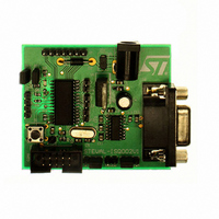
STEVAL-ISQ002V1
Description
BOARD EVAL BASED ON ST72264G1
Manufacturer
STMicroelectronics
Specifications of STEVAL-ISQ002V1
Main Purpose
Interface, PMBus
Embedded
Yes, MCU, 8-Bit
Utilized Ic / Part
ST72F264
Primary Attributes
The PMBus™ Interface Using the ST7 I2C Peripheral
Secondary Attributes
Firmware in C Language
Product
Power Management Modules
Lead Free Status / RoHS Status
Lead free / RoHS Compliant
Other names
497-6423
Available stocks
Company
Part Number
Manufacturer
Quantity
Price
Company:

Part Number:
STEVAL-ISQ002V1
Manufacturer:
STMicroelectronics
Quantity:
1


ST72260Gx, ST72262Gx, ST72264Gx
I
11.6.7 Register Description
I
Read / Write
Reset Value: 0000 0000 (00h)
Bit 7:6 = Reserved. Forced to 0 by hardware.
Bit 5 = PE Peripheral enable.
This bit is set and cleared by software.
0: Peripheral disabled
1: Master/Slave capability
Notes:
– When PE=0, all the bits of the CR register and
– When PE=1, the corresponding I/O pins are se-
– To enable the I
Bit 4 = ENGC Enable General Call.
This bit is set and cleared by software. It is also
cleared by hardware when the interface is disa-
bled (PE=0). The 00h General Call address is ac-
knowledged (01h ignored).
0: General Call disabled
1: General Call enabled
Note: In accordance with the I2C standard, when
GCAL addressing is enabled, an I2C slave can
only receive data. It will not transmit data to the
master.
Bit 3 = START Generation of a Start condition.
This bit is set and cleared by software. It is also
cleared by hardware when the interface is disa-
bled (PE=0) or when the Start condition is sent
(with interrupt generation if ITE=1).
– In master mode:
110/172
2
2
C BUS INTERFACE (Cont’d)
C CONTROL REGISTER (CR)
the SR register except the Stop bit are reset. All
outputs are released while PE=0
lected by hardware as alternate functions.
TWICE with PE=1 as the first write only activates
the interface (only PE is set).
0: No start generation
1: Repeated start generation
7
0
0
PE
2
C interface, write the CR register
ENGC START ACK
STOP
ITE
0
– In slave mode:
Bit 2 = ACK Acknowledge enable.
This bit is set and cleared by software. It is also
cleared by hardware when the interface is disa-
bled (PE=0).
0: No acknowledge returned
1: Acknowledge returned after an address byte or
Bit 1 = STOP Generation of a Stop condition.
This bit is set and cleared by software. It is also
cleared by hardware in master mode. Note: This
bit is not cleared when the interface is disabled
(PE=0).
– In master mode:
– In slave mode:
Bit 0 = ITE Interrupt enable.
This bit is set and cleared by software and cleared
by hardware when the interface is disabled
(PE=0).
0: Interrupts disabled
1: Interrupts enabled
Refer to
events and the interrupt.
SCL is held low when the ADD10, SB, BTF or
ADSL flags or an EV6 event (See
tected.
0: No start generation
1: Start generation when the bus is free
0: No stop generation
1: Stop generation after the current byte transfer
or after the current Start condition is sent. The
STOP bit is cleared by hardware when the Stop
condition is sent.
0: No stop generation
1: Release the SCL and SDA lines after the cur-
rent byte transfer (BTF=1). In this mode the
STOP bit has to be cleared by software.
a data byte is received
Figure 60
for the relationship between the
Figure
59) is de-
Related parts for STEVAL-ISQ002V1
Image
Part Number
Description
Manufacturer
Datasheet
Request
R

Part Number:
Description:
BOARD RGB CTR ST7,STP08C596MTR
Manufacturer:
STMicroelectronics
Datasheet:

Part Number:
Description:
Power Management IC Development Tools Full Speed USB to RS232 Bridge Demo
Manufacturer:
STMicroelectronics
Datasheet:
Part Number:
Description:
Power Management IC Development Tools 2.5W solar eval BRD USB SPV1040 LD39050
Manufacturer:
STMicroelectronics
Datasheet:

Part Number:
Description:
BOARD EVAL FOR MEMS SENSORS
Manufacturer:
STMicroelectronics
Datasheet:

Part Number:
Description:
KIT DEV STARTER ST10F276Z5
Manufacturer:
STMicroelectronics
Datasheet:

Part Number:
Description:
BOARD EVAL HDMI $ VIDEO SWITCH
Manufacturer:
STMicroelectronics
Datasheet:

Part Number:
Description:
BOARD DEMO ACCELEROMETER DIL24
Manufacturer:
STMicroelectronics
Datasheet:

Part Number:
Description:
BOARD STLM75/STDS75/ST72F651
Manufacturer:
STMicroelectronics
Datasheet:

Part Number:
Description:
EVAL BOARD 3AXIS MEMS ACCELLRMTR
Manufacturer:
STMicroelectronics
Datasheet:

Part Number:
Description:
BOARD EVAL 8BIT MICRO + TDE1708
Manufacturer:
STMicroelectronics
Datasheet:
Part Number:
Description:
STMicroelectronics [RIPPLE-CARRY BINARY COUNTER/DIVIDERS]
Manufacturer:
STMicroelectronics
Datasheet:
Part Number:
Description:
STMicroelectronics [LIQUID-CRYSTAL DISPLAY DRIVERS]
Manufacturer:
STMicroelectronics
Datasheet:
Part Number:
Description:
BOARD EVAL FOR MEMS SENSORS
Manufacturer:
STMicroelectronics
Datasheet: