STEVAL-ISQ002V1 STMicroelectronics, STEVAL-ISQ002V1 Datasheet - Page 55
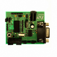
STEVAL-ISQ002V1
Manufacturer Part Number
STEVAL-ISQ002V1
Description
BOARD EVAL BASED ON ST72264G1
Manufacturer
STMicroelectronics
Specifications of STEVAL-ISQ002V1
Main Purpose
Interface, PMBus
Embedded
Yes, MCU, 8-Bit
Utilized Ic / Part
ST72F264
Primary Attributes
The PMBus™ Interface Using the ST7 I2C Peripheral
Secondary Attributes
Firmware in C Language
Product
Power Management Modules
Lead Free Status / RoHS Status
Lead free / RoHS Compliant
Other names
497-6423
Available stocks
Company
Part Number
Manufacturer
Quantity
Price
Company:

Part Number:
STEVAL-ISQ002V1
Manufacturer:
STMicroelectronics
Quantity:
1


11.3 16-BIT TIMER
11.3.1 Introduction
The timer consists of a 16-bit free-running counter
driven by a programmable prescaler.
It may be used for a variety of purposes, including
pulse length measurement of up to two input sig-
nals (input capture) or generation of up to two out-
put waveforms (output compare and PWM).
Pulse lengths and waveform periods can be mod-
ulated from a few microseconds to several milli-
seconds using the timer prescaler and the CPU
clock prescaler.
Some devices of the ST7 family have two on-chip
16-bit timers. They are completely independent,
and do not share any resources. They are syn-
chronized after a Device reset as long as the timer
clock frequencies are not modified.
This description covers one or two 16-bit timers. In
the devices with two timers, register names are
prefixed with TA (Timer A) or TB (Timer B).
11.3.2 Main Features
■
■
■
■
■
■
■
■
■
The Block Diagram is shown in
*Note: Some timer pins may not available (not
bonded) in some devices. Refer to the device pin
out description.
– 2 dedicated 16-bit registers
– 2 dedicated programmable signals
– 2 dedicated status flags
– 1 dedicated maskable interrupt
– 2 dedicated 16-bit registers
– 2 dedicated active edge selection signals
– 2 dedicated status flags
– 1 dedicated maskable interrupt
Programmable prescaler: f
Overflow status flag and maskable interrupt
External clock input (must be at least 4 times
slower than the CPU clock speed) with the choice
of active edge
Output compare functions with
Input capture functions with
Pulse width modulation mode (PWM)
One pulse mode
Reduced Power Mode
5 alternate functions on I/O ports (ICAP1, ICAP2,
OCMP1, OCMP2, EXTCLK)*
CPU
divided by 2, 4 or 8.
Figure
35.
When reading an input signal on a non-bonded
pin, the value will always be ‘1’.
11.3.3 Functional Description
11.3.3.1 Counter
The main block of the Programmable Timer is a
16-bit free running upcounter and its associated
16-bit registers. The 16-bit registers are made up
of two 8-bit registers called high & low.
Counter Register (CR):
Alternate Counter Register (ACR)
These two read-only 16-bit registers contain the
same value but with the difference that reading the
ACLR register does not clear the TOF bit (Timer
overflow flag), located in the Status register, (SR),
(see note at the end of paragraph titled 16-bit read
sequence).
Writing in the CLR register or ACLR register resets
the free running counter to the FFFCh value.
Both counters have a reset value of FFFCh (this is
the only value which is reloaded in the 16-bit tim-
er). The reset value of both counters is also
FFFCh in One Pulse mode and PWM mode.
The timer clock depends on the clock control bits
of the CR2 register, as illustrated in
Control
peats every 131 072, 262 144 or 524 288 CPU
clock cycles depending on the CC[1:0] bits.
The timer frequency can be f
or an external frequency.
– Counter High Register (CHR) is the most sig-
– Counter Low Register (CLR) is the least sig-
– Alternate Counter High Register (ACHR) is the
– Alternate Counter Low Register (ACLR) is the
nificant byte (MS Byte).
nificant byte (LS Byte).
m ost significant byte (MS Byte).
least significant byte (LS Byte ).
ST72260Gx, ST72262Gx, ST72264Gx
Bits. The value in the counter register re-
CPU
/2, f
Table 14 Clock
CPU
/4, f
55/172
CPU
/8
Related parts for STEVAL-ISQ002V1
Image
Part Number
Description
Manufacturer
Datasheet
Request
R

Part Number:
Description:
BOARD RGB CTR ST7,STP08C596MTR
Manufacturer:
STMicroelectronics
Datasheet:

Part Number:
Description:
Power Management IC Development Tools Full Speed USB to RS232 Bridge Demo
Manufacturer:
STMicroelectronics
Datasheet:
Part Number:
Description:
Power Management IC Development Tools 2.5W solar eval BRD USB SPV1040 LD39050
Manufacturer:
STMicroelectronics
Datasheet:

Part Number:
Description:
BOARD EVAL FOR MEMS SENSORS
Manufacturer:
STMicroelectronics
Datasheet:

Part Number:
Description:
KIT DEV STARTER ST10F276Z5
Manufacturer:
STMicroelectronics
Datasheet:

Part Number:
Description:
BOARD EVAL HDMI $ VIDEO SWITCH
Manufacturer:
STMicroelectronics
Datasheet:

Part Number:
Description:
BOARD DEMO ACCELEROMETER DIL24
Manufacturer:
STMicroelectronics
Datasheet:

Part Number:
Description:
BOARD STLM75/STDS75/ST72F651
Manufacturer:
STMicroelectronics
Datasheet:

Part Number:
Description:
EVAL BOARD 3AXIS MEMS ACCELLRMTR
Manufacturer:
STMicroelectronics
Datasheet:

Part Number:
Description:
BOARD EVAL 8BIT MICRO + TDE1708
Manufacturer:
STMicroelectronics
Datasheet:
Part Number:
Description:
STMicroelectronics [RIPPLE-CARRY BINARY COUNTER/DIVIDERS]
Manufacturer:
STMicroelectronics
Datasheet:
Part Number:
Description:
STMicroelectronics [LIQUID-CRYSTAL DISPLAY DRIVERS]
Manufacturer:
STMicroelectronics
Datasheet:
Part Number:
Description:
BOARD EVAL FOR MEMS SENSORS
Manufacturer:
STMicroelectronics
Datasheet: