STEVAL-ISQ002V1 STMicroelectronics, STEVAL-ISQ002V1 Datasheet - Page 36
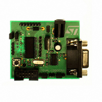
STEVAL-ISQ002V1
Manufacturer Part Number
STEVAL-ISQ002V1
Description
BOARD EVAL BASED ON ST72264G1
Manufacturer
STMicroelectronics
Specifications of STEVAL-ISQ002V1
Main Purpose
Interface, PMBus
Embedded
Yes, MCU, 8-Bit
Utilized Ic / Part
ST72F264
Primary Attributes
The PMBus™ Interface Using the ST7 I2C Peripheral
Secondary Attributes
Firmware in C Language
Product
Power Management Modules
Lead Free Status / RoHS Status
Lead free / RoHS Compliant
Other names
497-6423
Available stocks
Company
Part Number
Manufacturer
Quantity
Price
Company:

Part Number:
STEVAL-ISQ002V1
Manufacturer:
STMicroelectronics
Quantity:
1


ST72260Gx, ST72262Gx, ST72264Gx
POWER SAVING MODES (Cont’d)
8.5 HALT MODE
The HALT mode is the lowest power consumption
mode of the MCU. It is entered by executing the
ST7 HALT instruction (see
The MCU can exit HALT mode on reception of ei-
ther a specific interrupt (see
Mapping,” on page
HALT mode by means of a RESET or an interrupt,
the oscillator is immediately turned on and the
4096 CPU cycle delay is used to stabilize the os-
cillator. After the start up delay, the CPU resumes
operation by servicing the interrupt or by fetching
the reset vector which woke it up (see
When entering HALT mode, the I[1:0] bits in the
CC register are forced to ‘10b’ to enable interrupts.
Therefore, if an interrupt is pending, the MCU
wakes immediately.
In the HALT mode the main oscillator is turned off
causing all internal processing to be stopped, in-
cluding the operation of the on-chip peripherals.
All peripherals are not clocked except the ones
which get their clock supply from another clock
generator (such as an external or auxiliary oscilla-
tor).
The compatibility of Watchdog operation with
HALT mode is configured by the “WDGHALT” op-
tion bit of the option byte. The HALT instruction
when executed while the Watchdog system is en-
abled, can generate a Watchdog RESET (see
Section 15.1 "OPTION BYTES" on page 162
more details).
Figure 25. HALT Mode Timing Overview
36/172
INSTRUCTION
RUN
HALT
HALT
INTERRUPT
RESET
OR
4096 CPU CYCLE
32) or a RESET. When exiting
DELAY
Figure
Table 5, “Interrupt
26).
VECTOR
FETCH
Figure
RUN
25).
for
Figure 26. HALT Mode Flowchart
Notes:
1. WDGHALT is an option bit. See option byte sec-
tion for more details.
2. Peripheral clocked with an external clock source
can still be active.
3. Only some specific interrupts can exit the MCU
from HALT mode (such as external interrupt). Re-
fer to
more details.
4. Before servicing an interrupt, the CC register is
pushed on the stack. The I[1:0]
ister are set during the interrupt routine and
cleared when the CC register is popped.
N
HALT INSTRUCTION
WATCHDOG
WDGHALT
Table 5, “Interrupt Mapping,” on page 32
RESET
1
INTERRUPT
Y
1)
3)
ENABLE
4096 CPU CLOCK CYCLE
OR SERVICE INTERRUPT
0
FETCH RESET VECTOR
OSCILLATOR
PERIPHERALS
CPU
I[1:0] BITS
OSCILLATOR
PERIPHERALS
CPU
I[1:0] BITS
OSCILLATOR
PERIPHERALS
CPU
I[1:0] BITS
N
DELAY
bits
RESET
Y
WATCHDOG
in the CC reg-
DISABLE
2)
XX
OFF
OFF
OFF
OFF
ON
ON
ON
ON
ON
0
1
4)
for
Related parts for STEVAL-ISQ002V1
Image
Part Number
Description
Manufacturer
Datasheet
Request
R

Part Number:
Description:
BOARD RGB CTR ST7,STP08C596MTR
Manufacturer:
STMicroelectronics
Datasheet:

Part Number:
Description:
Power Management IC Development Tools Full Speed USB to RS232 Bridge Demo
Manufacturer:
STMicroelectronics
Datasheet:
Part Number:
Description:
Power Management IC Development Tools 2.5W solar eval BRD USB SPV1040 LD39050
Manufacturer:
STMicroelectronics
Datasheet:

Part Number:
Description:
BOARD EVAL FOR MEMS SENSORS
Manufacturer:
STMicroelectronics
Datasheet:

Part Number:
Description:
KIT DEV STARTER ST10F276Z5
Manufacturer:
STMicroelectronics
Datasheet:

Part Number:
Description:
BOARD EVAL HDMI $ VIDEO SWITCH
Manufacturer:
STMicroelectronics
Datasheet:

Part Number:
Description:
BOARD DEMO ACCELEROMETER DIL24
Manufacturer:
STMicroelectronics
Datasheet:

Part Number:
Description:
BOARD STLM75/STDS75/ST72F651
Manufacturer:
STMicroelectronics
Datasheet:

Part Number:
Description:
EVAL BOARD 3AXIS MEMS ACCELLRMTR
Manufacturer:
STMicroelectronics
Datasheet:

Part Number:
Description:
BOARD EVAL 8BIT MICRO + TDE1708
Manufacturer:
STMicroelectronics
Datasheet:
Part Number:
Description:
STMicroelectronics [RIPPLE-CARRY BINARY COUNTER/DIVIDERS]
Manufacturer:
STMicroelectronics
Datasheet:
Part Number:
Description:
STMicroelectronics [LIQUID-CRYSTAL DISPLAY DRIVERS]
Manufacturer:
STMicroelectronics
Datasheet:
Part Number:
Description:
BOARD EVAL FOR MEMS SENSORS
Manufacturer:
STMicroelectronics
Datasheet: