STEVAL-PSQ001V1 STMicroelectronics, STEVAL-PSQ001V1 Datasheet - Page 20
STEVAL-PSQ001V1
Manufacturer Part Number
STEVAL-PSQ001V1
Description
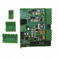
BOARD EVAL BASED ON PM6680A
Manufacturer
STMicroelectronics
Type
Other Power Managementr
Specifications of STEVAL-PSQ001V1
Design Resources
STEVAL-PSQ001V1 Gerber Files STEVAL-PSQ001V1 Schematic STEVAL-PSQ001V1 Bill of Material
Main Purpose
DC/DC, Step Down with LDO
Outputs And Type
6, Non-Isolated
Voltage - Output
0.9 ~ 2.5 V, 1 ~ 3.3 V, 2x 3.3 V, 2.5 V, 5 V
Current - Output
4A, 2A, 800mA, 400mA, 400mA, 150mA
Voltage - Input
5 ~ 36V
Regulator Topology
Buck
Frequency - Switching
200kHz, 300kHz
Board Type
Fully Populated
Utilized Ic / Part
PM6680A
Input Voltage
5 V to 36 V
Output Voltage
1 V to 3.3 V
Product
Power Management Modules
Silicon Manufacturer
ST Micro
Silicon Core Number
PM6680A
Kit Application Type
Power Management
Application Sub Type
Power Supply
Kit Contents
Board
Rohs Compliant
Yes
Lead Free Status / RoHS Status
Lead free / RoHS Compliant
Power - Output
-
Lead Free Status / Rohs Status
Lead free / RoHS Compliant
For Use With/related Products
PM6680A
Other names
497-6425
STEVAL-PSQ001V1
STEVAL-PSQ001V1


Device description
7.2
20/48
Constant on time architecture
Figure 29
off-time constrain (350 ns typ.) is introduced to allow inductor valley current sensing on
synchronous switch. A minimum on-time (130 ns) is also introduced to assure the start-up
switching sequence.
PM6680A has a one-shot generator for each power section that turns on the high side
MOSFET when the following conditions are satisfied simultaneously: the PWM comparator
is high, the synchronous rectifier current is below the current limit threshold, and the
minimum off-time has timed out.
Once the on-time has timed out, the high side switch is turned off, while the synchronous
switch is turned on according to the anti-cross conduction circuitry management.
When the negative input voltage at the PWM comparator
down replica of the output voltage (see the external R1/R2 divider in
valley limit (determined by internal reference Vr = 0.9 V), the low-side MOSFET is turned off
according to the anti-cross conduction logic once again, and a new cycle begins.
Figure 29. Constant on-time block diagram
In steady state the FB pin voltage is about Vr and the regulated output voltage depends on
the external divider:
Equation 4
shows the simplified block diagram of a constant on time controller. A minimum
OUT
=
Vr
×
⎛
⎝
1
+
R
------ -
R
2
1
⎞
⎠
(Figure
29), which is a scaled-
Figure
29), reaches the
PM6680A
Related parts for STEVAL-PSQ001V1
Image
Part Number
Description
Manufacturer
Datasheet
Request
R

Part Number:
Description:
BOARD ELECT FISCAL CASH REGISTER
Manufacturer:
STMicroelectronics
Datasheet:

Part Number:
Description:
BOARD DEMO LNB PS LNBH23L QFN
Manufacturer:
STMicroelectronics
Datasheet:

Part Number:
Description:
BOARD DEMONSTRATION LNBH PS
Manufacturer:
STMicroelectronics
Datasheet:

Part Number:
Description:
BOARD EVAL FOR MEMS SENSORS
Manufacturer:
STMicroelectronics
Datasheet:
Part Number:
Description:
EVALBOARD/STEVAL-ISV014V1
Manufacturer:
STMicroelectronics
Part Number:
Description:
BOARD EVAL FOR ST802RT1
Manufacturer:
STMicroelectronics
Datasheet:

Part Number:
Description:
BOARD EVAL FOR VACUUM CLEANER
Manufacturer:
STMicroelectronics
Datasheet:

Part Number:
Description:
KIT DEV STARTER ST10F276Z5
Manufacturer:
STMicroelectronics
Datasheet:

Part Number:
Description:
BOARD LED CTLR/DVR STLED316S
Manufacturer:
STMicroelectronics
Datasheet:

Part Number:
Description:
BOARD EVAL BLDC SENSORLESS MOTOR
Manufacturer:
STMicroelectronics
Datasheet:
Part Number:
Description:
STMicroelectronics [RIPPLE-CARRY BINARY COUNTER/DIVIDERS]
Manufacturer:
STMicroelectronics
Datasheet:
Part Number:
Description:
STMicroelectronics [LIQUID-CRYSTAL DISPLAY DRIVERS]
Manufacturer:
STMicroelectronics
Datasheet:
Part Number:
Description:
BOARD EVAL FOR MEMS SENSORS
Manufacturer:
STMicroelectronics
Datasheet: