STEVAL-PSQ001V1 STMicroelectronics, STEVAL-PSQ001V1 Datasheet - Page 25
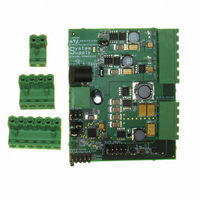
STEVAL-PSQ001V1
Manufacturer Part Number
STEVAL-PSQ001V1
Description
BOARD EVAL BASED ON PM6680A
Manufacturer
STMicroelectronics
Type
Other Power Managementr
Specifications of STEVAL-PSQ001V1
Design Resources
STEVAL-PSQ001V1 Gerber Files STEVAL-PSQ001V1 Schematic STEVAL-PSQ001V1 Bill of Material
Main Purpose
DC/DC, Step Down with LDO
Outputs And Type
6, Non-Isolated
Voltage - Output
0.9 ~ 2.5 V, 1 ~ 3.3 V, 2x 3.3 V, 2.5 V, 5 V
Current - Output
4A, 2A, 800mA, 400mA, 400mA, 150mA
Voltage - Input
5 ~ 36V
Regulator Topology
Buck
Frequency - Switching
200kHz, 300kHz
Board Type
Fully Populated
Utilized Ic / Part
PM6680A
Input Voltage
5 V to 36 V
Output Voltage
1 V to 3.3 V
Product
Power Management Modules
Silicon Manufacturer
ST Micro
Silicon Core Number
PM6680A
Kit Application Type
Power Management
Application Sub Type
Power Supply
Kit Contents
Board
Rohs Compliant
Yes
Lead Free Status / RoHS Status
Lead free / RoHS Compliant
Power - Output
-
Lead Free Status / Rohs Status
Lead free / RoHS Compliant
For Use With/related Products
PM6680A
Other names
497-6425
STEVAL-PSQ001V1
STEVAL-PSQ001V1


PM6680A
7.7
Being fixed the valley threshold, the greater the current ripple is, greater the DC output
current is The valley current limit can be set with resistor RCSENSE:
Equation 7
Where I
Consider the temperature effect and the worst case value in RDSon calculation.
The accuracy of the valley current threshold detection depends on the offset of the internal
comparator (∆V
Equation 8
Where RSNS is the sensing element(RDSon)
PM6680A provides also a fixed negative peak current limit to prevent an excessive reverse
inductor current when the switching section sinks current from the load in PWM mode. This
negative current limit threshold is measured between PHASE and SGND pins, comparing
the magnitude drop on the PHASE node during the conduction time of the low side
MOSFET with an internal fixed voltage of 120 mV.
The negative valley-current limit I
Equation 9
Soft start and soft end
Each switching section is enabled separately by asserting high EN1/EN2 pins respectively.
In order to realize the soft start, at the startup the overcurrent threshold is set 25 % of the
nominal value and the undervoltage protection (see related sections) is disabled. The
controller starts charging the output capacitor working in current limit. The overcurrent
threshold is increased from 25 % to 100 % of the nominal value with steps of 25 % every
700 µs (typ.). After 2.8 ms (typ.) the undervoltage protection is enabled. The soft start time is
not programmable. A minimum capacitor C
overshoot on the output:
Equation 10
CSENSE
∆
I
I
Lvalley
Lvalley
OFF
= 100 µA, RDSon is the drain-source on resistance of the low side switch.
=
) and on the accuracy of the current generator (∆I
∆
I
I
CSENSE
CSENSE
+
R
NEG
C
⎡
⎢
⎣
CSENSE
R
INT
CSENSE
(if the device works in PWM mode) is given by:
I
≥
NEG
∆
I
Lvalley
=
V
×
4
OFF
R
---------------------------------------------
=
INT
6
I
DS on
µ
120
CSENSE
A
+
R
is required to ensure a soft start without any
(
Icsense
DSon
∆
mV
2
)
I
L
×
×
I
×
Lvalley
100
C
out
⎤
⎥
⎦
+
∆
R
R
CSENSE
CSENSE
CSENSE
Device description
+
∆
R
)
R
SNS
SNS
25/48
Related parts for STEVAL-PSQ001V1
Image
Part Number
Description
Manufacturer
Datasheet
Request
R

Part Number:
Description:
BOARD ELECT FISCAL CASH REGISTER
Manufacturer:
STMicroelectronics
Datasheet:

Part Number:
Description:
BOARD DEMO LNB PS LNBH23L QFN
Manufacturer:
STMicroelectronics
Datasheet:

Part Number:
Description:
BOARD DEMONSTRATION LNBH PS
Manufacturer:
STMicroelectronics
Datasheet:

Part Number:
Description:
BOARD EVAL FOR MEMS SENSORS
Manufacturer:
STMicroelectronics
Datasheet:
Part Number:
Description:
EVALBOARD/STEVAL-ISV014V1
Manufacturer:
STMicroelectronics
Part Number:
Description:
BOARD EVAL FOR ST802RT1
Manufacturer:
STMicroelectronics
Datasheet:

Part Number:
Description:
BOARD EVAL FOR VACUUM CLEANER
Manufacturer:
STMicroelectronics
Datasheet:

Part Number:
Description:
KIT DEV STARTER ST10F276Z5
Manufacturer:
STMicroelectronics
Datasheet:

Part Number:
Description:
BOARD LED CTLR/DVR STLED316S
Manufacturer:
STMicroelectronics
Datasheet:

Part Number:
Description:
BOARD EVAL BLDC SENSORLESS MOTOR
Manufacturer:
STMicroelectronics
Datasheet:
Part Number:
Description:
STMicroelectronics [RIPPLE-CARRY BINARY COUNTER/DIVIDERS]
Manufacturer:
STMicroelectronics
Datasheet:
Part Number:
Description:
STMicroelectronics [LIQUID-CRYSTAL DISPLAY DRIVERS]
Manufacturer:
STMicroelectronics
Datasheet:
Part Number:
Description:
BOARD EVAL FOR MEMS SENSORS
Manufacturer:
STMicroelectronics
Datasheet: