PIC16F690DM-PCTLHS Microchip Technology, PIC16F690DM-PCTLHS Datasheet - Page 133
PIC16F690DM-PCTLHS
Manufacturer Part Number
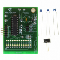
PIC16F690DM-PCTLHS
Description
BOARD DEMO PICTAIL HUMIDITY SNSR
Manufacturer
Microchip Technology
Series
PICtail™r
Datasheets
1.PIC16F690DM-PCTLHS.pdf
(36 pages)
2.PIC16F690DM-PCTLHS.pdf
(32 pages)
3.PIC16F690DM-PCTLHS.pdf
(306 pages)
4.PIC16F690DM-PCTLHS.pdf
(14 pages)
Specifications of PIC16F690DM-PCTLHS
Sensor Type
Humidity
Sensing Range
1 ~ 99% RH
Interface
Analog
Voltage - Supply
5V
Embedded
Yes, MCU, 8-Bit
Utilized Ic / Part
MCP6291, PIC16F690
Processor To Be Evaluated
MCP6291 and PIC16F690
Interface Type
ICSP
Lead Free Status / RoHS Status
Lead free / RoHS Compliant
For Use With
AC162061 - HEADER INTRFC MPLAB ICD2 20PIN
Sensitivity
-
Lead Free Status / RoHS Status
Lead free / RoHS Compliant, Lead free / RoHS Compliant


11.3.1
The PWM period is specified by the PR2 register of
Timer2. The PWM period can be calculated using the
formula of Equation 11-1.
EQUATION 11-1:
When TMR2 is equal to PR2, the following three events
occur on the next increment cycle:
• TMR2 is cleared
• The CCP1 pin is set. (Exception: If the PWM duty
• The PWM duty cycle is latched from CCPR1L into
11.3.2
The PWM duty cycle is specified by writing a 10-bit
value to multiple registers: CCPR1L register and
DC1B<1:0> bits of the CCP1CON register. The
CCPR1L contains the eight MSbs and the DC1B<1:0>
bits of the CCP1CON register contain the two LSbs.
CCPR1L and DC1B<1:0> bits of the CCP1CON
register can be written to at any time. The duty cycle
value is not latched into CCPR1H until after the period
completes (i.e., a match between PR2 and TMR2
registers occurs). While using the PWM, the CCPR1H
register is read-only.
Equation 11-2 is used to calculate the PWM pulse
width.
Equation 11-3 is used to calculate the PWM duty cycle
ratio.
TABLE 11-2:
TABLE 11-3:
© 2008 Microchip Technology Inc.
Timer Prescale (1, 4, 16)
PR2 Value
Maximum Resolution (bits)
Timer Prescale (1, 4, 16)
PR2 Value
Maximum Resolution (bits)
cycle = 0%, the pin will not be set.)
CCPR1H.
Note:
Note:
PWM Period
PWM Frequency
PWM Frequency
PWM PERIOD
The Timer2 postscaler (see Section 7.1
“Timer2 Operation”) is not used in the
determination of the PWM frequency.
PWM DUTY CYCLE
T
OSC
EXAMPLE PWM FREQUENCIES AND RESOLUTIONS (F
EXAMPLE PWM FREQUENCIES AND RESOLUTIONS (F
=
= 1/F
(TMR2 Prescale Value)
[
PWM PERIOD
(
PR2
OSC
)
+
1
] 4 T
1.22 kHz
1.22 kHz
•
PIC16F631/677/685/687/689/690
0xFF
0x65
16
10
16
•
8
OSC
•
4.88 kHz
4.90 kHz
0xFF
0x65
10
4
4
8
19.53 kHz
19.61 kHz
EQUATION 11-2:
EQUATION 11-3:
The CCPR1H register and a 2-bit internal latch are
used to double buffer the PWM duty cycle. This double
buffering is essential for glitchless PWM operation.
The 8-bit timer TMR2 register is concatenated with
either the 2-bit internal system clock (F
the prescaler, to create the 10-bit time base. The system
clock is used if the Timer2 prescaler is set to 1:1.
When the 10-bit time base matches the CCPR1H and
2-bit latch, then the CCP1 pin is cleared (see
Figure 11-3).
11.3.3
The resolution determines the number of available duty
cycles for a given period. For example, a 10-bit resolution
will result in 1024 discrete duty cycles, whereas an 8-bit
resolution will result in 256 discrete duty cycles.
The maximum PWM resolution is 10 bits when PR2 is
255. The resolution is a function of the PR2 register
value as shown by Equation 11-4.
EQUATION 11-4:
Note:
0xFF
0x65
Duty Cycle Ratio
10
1
1
8
Pulse Width
Resolution
If the pulse width value is greater than the
period the assigned PWM pin(s) will
remain unchanged.
PWM RESOLUTION
78.12 kHz
76.92 kHz
=
0x3F
0x19
1
8
1
6
(
T
=
CCPR1L:CCP1CON<5:4>
OSC
OSC
=
OSC
PULSE WIDTH
DUTY CYCLE RATIO
PWM RESOLUTION
(
---------------------------------------------------------------------- -
CCPR1L:CCP1CON<5:4>
log
----------------------------------------- - bits
= 20 MHz)
= 8 MHz)
•
[
4 PR2
153.85 kHz
log
156.3 kHz
(
(TMR2 Prescale Value)
4 PR2
0x0C
0x1F
2 ( )
(
1
7
1
5
+
DS41262E-page 131
1
+
)
OSC
]
1
)
), or 2 bits of
208.3 kHz
200.0 kHz
0x17
0x09
)
6.6
1
1
5
•
)
Related parts for PIC16F690DM-PCTLHS
Image
Part Number
Description
Manufacturer
Datasheet
Request
R

Part Number:
Description:
Manufacturer:
Microchip Technology Inc.
Datasheet:
Part Number:
Description:
Manufacturer:
Microchip Technology Inc.
Datasheet:
Part Number:
Description:
Manufacturer:
Microchip Technology Inc.
Datasheet:
Part Number:
Description:
Manufacturer:
Microchip Technology Inc.
Datasheet:
Part Number:
Description:
Manufacturer:
Microchip Technology Inc.
Datasheet:
Part Number:
Description:
Manufacturer:
Microchip Technology Inc.
Datasheet:
Part Number:
Description:
Manufacturer:
Microchip Technology Inc.
Datasheet:
Part Number:
Description:
Manufacturer:
Microchip Technology Inc.
Datasheet: