PIC16F690DM-PCTLHS Microchip Technology, PIC16F690DM-PCTLHS Datasheet - Page 65
PIC16F690DM-PCTLHS
Manufacturer Part Number
PIC16F690DM-PCTLHS
Description
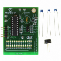
BOARD DEMO PICTAIL HUMIDITY SNSR
Manufacturer
Microchip Technology
Series
PICtail™r
Datasheets
1.PIC16F690DM-PCTLHS.pdf
(36 pages)
2.PIC16F690DM-PCTLHS.pdf
(32 pages)
3.PIC16F690DM-PCTLHS.pdf
(306 pages)
4.PIC16F690DM-PCTLHS.pdf
(14 pages)
Specifications of PIC16F690DM-PCTLHS
Sensor Type
Humidity
Sensing Range
1 ~ 99% RH
Interface
Analog
Voltage - Supply
5V
Embedded
Yes, MCU, 8-Bit
Utilized Ic / Part
MCP6291, PIC16F690
Processor To Be Evaluated
MCP6291 and PIC16F690
Interface Type
ICSP
Lead Free Status / RoHS Status
Lead free / RoHS Compliant
For Use With
AC162061 - HEADER INTRFC MPLAB ICD2 20PIN
Sensitivity
-
Lead Free Status / RoHS Status
Lead free / RoHS Compliant, Lead free / RoHS Compliant


4.2.4
The Ultra Low-Power Wake-up (ULPWU) on RA0 allows
a slow falling voltage to generate an interrupt-on-change
on RA0 without excess current consumption. The mode
is selected by setting the ULPWUE bit of the PCON
register. This enables a small current sink, which can be
used to discharge a capacitor on RA0.
Follow these steps to use this feature:
a)
b)
c)
d)
e)
will be generated which will cause the device to
wake-up and execute the next instruction. If the GIE bit
of the INTCON register is set, the device will then call
the interrupt vector (0004h). See Section 4.4.2 “Inter-
rupt-on-change”
“PORTA/PORTB Interrupt” for more information.
This feature provides a low-power technique for
periodically waking up the device from Sleep. The
time-out is dependent on the discharge time of the RC
circuit on RA0. See Example 4-2 for initializing the
Ultra Low-Power Wake-up module.
© 2008 Microchip Technology Inc.
When the voltage on RA0 drops below V
Charge the capacitor on RA0 by configuring the
RA0 pin to output (= 1).
Configure RA0 as an input.
Enable interrupt-on-change for RA0.
Set the ULPWUE bit of the PCON register to
begin the capacitor discharge.
Execute a SLEEP instruction.
ULTRA LOW-POWER WAKE-UP
and
PIC16F631/677/685/687/689/690
Section 14.3.3
IL
, an interrupt
A series resistor between RA0 and the external
capacitor provides overcurrent protection for the
RA0/AN0/C1IN+/ICSPDAT/ULPWU pin and can allow
for software calibration of the time-out (see Figure 4-1).
A timer can be used to measure the charge time and
discharge time of the capacitor. The charge time can
then be adjusted to provide the desired interrupt delay.
This technique will compensate for the affects of
temperature, voltage and component accuracy. The
Ultra Low-Power Wake-up peripheral can also be
configured as a simple Programmable Low-Voltage
Detect or temperature sensor.
EXAMPLE 4-2:
BCF
BCF
BSF
BSF
BCF
BSF
BCF
BCF
CALL
BSF
BSF
BSF
MOVLW
MOVWF
BCF
SLEEP
NOP
Note:
STATUS,RP0
STATUS,RP1
PORTA,0
STATUS,RP1
ANSEL,0
STATUS,RP0
STATUS,RP1
TRISA,0
CapDelay
PCON,ULPWUE
IOCA,0
TRISA,0
B’10001000’
INTCON
STATUS,RP0
For more information, refer to Application
Note AN879, “Using the Microchip Ultra
Low-Power Wake-up Module” (DS00879).
ULTRA LOW-POWER
WAKE-UP INITIALIZATION
;Bank 0
;
;Set RA0 data latch
;Bank 2
;RA0 to digital I/O
;Bank 1
;
;Output high to
;charge capacitor
;Enable ULP Wake-up
;Select RA0 IOC
;RA0 to input
;Enable interrupt
;and clear flag
;Bank 0
;Wait for IOC
;
DS41262E-page 63
Related parts for PIC16F690DM-PCTLHS
Image
Part Number
Description
Manufacturer
Datasheet
Request
R

Part Number:
Description:
Manufacturer:
Microchip Technology Inc.
Datasheet:
Part Number:
Description:
Manufacturer:
Microchip Technology Inc.
Datasheet:
Part Number:
Description:
Manufacturer:
Microchip Technology Inc.
Datasheet:
Part Number:
Description:
Manufacturer:
Microchip Technology Inc.
Datasheet:
Part Number:
Description:
Manufacturer:
Microchip Technology Inc.
Datasheet:
Part Number:
Description:
Manufacturer:
Microchip Technology Inc.
Datasheet:
Part Number:
Description:
Manufacturer:
Microchip Technology Inc.
Datasheet:
Part Number:
Description:
Manufacturer:
Microchip Technology Inc.
Datasheet: