PIC16F690DM-PCTLHS Microchip Technology, PIC16F690DM-PCTLHS Datasheet - Page 78
PIC16F690DM-PCTLHS
Manufacturer Part Number
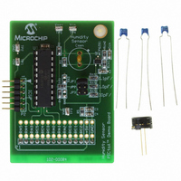
PIC16F690DM-PCTLHS
Description
BOARD DEMO PICTAIL HUMIDITY SNSR
Manufacturer
Microchip Technology
Series
PICtail™r
Datasheets
1.PIC16F690DM-PCTLHS.pdf
(36 pages)
2.PIC16F690DM-PCTLHS.pdf
(32 pages)
3.PIC16F690DM-PCTLHS.pdf
(306 pages)
4.PIC16F690DM-PCTLHS.pdf
(14 pages)
Specifications of PIC16F690DM-PCTLHS
Sensor Type
Humidity
Sensing Range
1 ~ 99% RH
Interface
Analog
Voltage - Supply
5V
Embedded
Yes, MCU, 8-Bit
Utilized Ic / Part
MCP6291, PIC16F690
Processor To Be Evaluated
MCP6291 and PIC16F690
Interface Type
ICSP
Lead Free Status / RoHS Status
Lead free / RoHS Compliant
For Use With
AC162061 - HEADER INTRFC MPLAB ICD2 20PIN
Sensitivity
-
Lead Free Status / RoHS Status
Lead free / RoHS Compliant, Lead free / RoHS Compliant


PIC16F631/677/685/687/689/690
4.5
PORTC is a 8-bit wide, bidirectional port. The
corresponding data direction register is TRISC (Register
4-10). Setting a TRISC bit (= 1) will make the
corresponding PORTC pin an input (i.e., put the
corresponding output driver in a High-Impedance mode).
Clearing a TRISC bit (= 0) will make the corresponding
PORTC pin an output (i.e., enable the output driver and
put the contents of the output latch on the selected pin).
Example 4-4 shows how to initialize PORTC. Reading
the PORTC register (Register 4-9) reads the status of the
pins, whereas writing to it will write to the PORT latch. All
write operations are read-modify-write operations.
Therefore, a write to a port implies that the port pins are
read, this value is modified and then written to the PORT
data latch.
REGISTER 4-11:
REGISTER 4-12:
DS41262E-page 76
bit 7
Legend:
R = Readable bit
-n = Value at POR
bit 7-0
bit 7
Legend:
R = Readable bit
-n = Value at POR
bit 7-0
TRISC7
R/W-1
R/W-0
RC7
PORTC and TRISC Registers
RC<7:0>: PORTC General Purpose I/O Pin bit
1 = Port pin is > V
0 = Port pin is < V
TRISC<7:0>: PORTC Tri-State Control bit
1 = PORTC pin configured as an input (tri-stated)
0 = PORTC pin configured as an output
TRISC6
R/W-1
R/W-x
RC6
PORTC: PORTC REGISTER
TRISC: PORTC TRI-STATE REGISTER
W = Writable bit
‘1’ = Bit is set
W = Writable bit
‘1’ = Bit is set
IH
IL
TRISC5
R/W-1
R/W-x
RC5
TRISC4
R/W-1
R/W-x
RC4
U = Unimplemented bit, read as ‘0’
‘0’ = Bit is cleared
U = Unimplemented bit, read as ‘0’
‘0’ = Bit is cleared
TRISC3
The TRISC register controls the PORTC pin output
drivers, even when they are being used as analog inputs.
The user should ensure the bits in the TRISC register are
maintained set when using them as analog inputs. I/O
pins configured as analog input always read ‘0’.
EXAMPLE 4-4:
R/W-x
BCF
BCF
CLRF
BSF
CLRF
BSF
BCF
MOVLW
MOVWF
BCF
RC3
R-1
Note:
STATUS,RP0
STATUS,RP1
PORTC
STATUS,RP1
ANSEL
STATUS,RP0
STATUS,RP1
0Ch
TRISC
STATUS,RP0
The ANSEL and ANSELH registers must
be initialized to configure an analog
channel as a digital input. Pins configured
as analog inputs will read ‘0’.
TRISC2
R/W-1
R/W-x
RC2
INITIALIZING PORTC
© 2008 Microchip Technology Inc.
;Bank 0
;
;Init PORTC
;Bank 2
;digital I/O
;Bank 1
;
;Set RC<3:2> as inputs
;and set RC<5:4,1:0>
;as outputs
;Bank 0
x = Bit is unknown
x = Bit is unknown
TRISC1
R/W-1
R/W-x
RC1
TRISC0
R/W-1
R/W-x
RC0
bit 0
bit 0
Related parts for PIC16F690DM-PCTLHS
Image
Part Number
Description
Manufacturer
Datasheet
Request
R

Part Number:
Description:
Manufacturer:
Microchip Technology Inc.
Datasheet:
Part Number:
Description:
Manufacturer:
Microchip Technology Inc.
Datasheet:
Part Number:
Description:
Manufacturer:
Microchip Technology Inc.
Datasheet:
Part Number:
Description:
Manufacturer:
Microchip Technology Inc.
Datasheet:
Part Number:
Description:
Manufacturer:
Microchip Technology Inc.
Datasheet:
Part Number:
Description:
Manufacturer:
Microchip Technology Inc.
Datasheet:
Part Number:
Description:
Manufacturer:
Microchip Technology Inc.
Datasheet:
Part Number:
Description:
Manufacturer:
Microchip Technology Inc.
Datasheet: