PIC16F690DM-PCTLHS Microchip Technology, PIC16F690DM-PCTLHS Datasheet - Page 142
PIC16F690DM-PCTLHS
Manufacturer Part Number
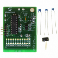
PIC16F690DM-PCTLHS
Description
BOARD DEMO PICTAIL HUMIDITY SNSR
Manufacturer
Microchip Technology
Series
PICtail™r
Datasheets
1.PIC16F690DM-PCTLHS.pdf
(36 pages)
2.PIC16F690DM-PCTLHS.pdf
(32 pages)
3.PIC16F690DM-PCTLHS.pdf
(306 pages)
4.PIC16F690DM-PCTLHS.pdf
(14 pages)
Specifications of PIC16F690DM-PCTLHS
Sensor Type
Humidity
Sensing Range
1 ~ 99% RH
Interface
Analog
Voltage - Supply
5V
Embedded
Yes, MCU, 8-Bit
Utilized Ic / Part
MCP6291, PIC16F690
Processor To Be Evaluated
MCP6291 and PIC16F690
Interface Type
ICSP
Lead Free Status / RoHS Status
Lead free / RoHS Compliant
For Use With
AC162061 - HEADER INTRFC MPLAB ICD2 20PIN
Sensitivity
-
Lead Free Status / RoHS Status
Lead free / RoHS Compliant, Lead free / RoHS Compliant


PIC16F631/677/685/687/689/690
FIGURE 11-13:
11.4.3
When any PWM mode is used, the application
hardware must use the proper external pull-up and/or
pull-down resistors on the PWM output pins.
The CCP1M<1:0> bits of the CCP1CON register allow
the user to choose whether the PWM output signals are
active-high or active-low for each pair of PWM output pins
(P1A/P1C and P1B/P1D). The PWM output polarities
must be selected before the PWM pin output drivers are
enabled. Changing the polarity configuration while the
PWM pin output drivers are enabled is not recommended
since it may result in damage to the application circuits.
The P1A, P1B, P1C and P1D output latches may not be
in the proper states when the PWM module is
initialized. Enabling the PWM pin output drivers at the
same time as the Enhanced PWM modes may cause
damage to the application circuit. The Enhanced PWM
modes must be enabled in the proper Output mode and
complete a full PWM cycle before enabling the PWM
pin output drivers. The completion of a full PWM cycle
is indicated by the TMR2IF bit of the PIR1 register
being set as the second PWM period begins.
DS41262E-page 140
Note:
Shoot-Through Current
Note 1: All signals are shown as active-high.
External Switch C
External Switch D
2: T
3: T
START-UP CONSIDERATIONS
When the microcontroller is released from
Reset, all of the I/O pins are in the
high-impedance state. The external cir-
cuits must keep the power switch devices
in the OFF state until the microcontroller
drives the I/O pins with the proper signal
levels or activates the PWM output(s).
ON
OFF
Potential
is the turn on delay of power switch QC and its driver.
is the turn off delay of power switch QD and its driver.
P1C
P1D
P1A
P1B
EXAMPLE OF PWM DIRECTION CHANGE AT NEAR 100% DUTY CYCLE
Forward Period
PW
t1
T
ON
Reverse Period
T
T = T
OFF
OFF
PW
© 2008 Microchip Technology Inc.
– T
ON
Related parts for PIC16F690DM-PCTLHS
Image
Part Number
Description
Manufacturer
Datasheet
Request
R

Part Number:
Description:
Manufacturer:
Microchip Technology Inc.
Datasheet:
Part Number:
Description:
Manufacturer:
Microchip Technology Inc.
Datasheet:
Part Number:
Description:
Manufacturer:
Microchip Technology Inc.
Datasheet:
Part Number:
Description:
Manufacturer:
Microchip Technology Inc.
Datasheet:
Part Number:
Description:
Manufacturer:
Microchip Technology Inc.
Datasheet:
Part Number:
Description:
Manufacturer:
Microchip Technology Inc.
Datasheet:
Part Number:
Description:
Manufacturer:
Microchip Technology Inc.
Datasheet:
Part Number:
Description:
Manufacturer:
Microchip Technology Inc.
Datasheet: