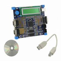
OM11014 NXP Semiconductors, OM11014 Datasheet - Page 43

OM11014
Manufacturer Part Number
OM11014
Description
BOARD EVAL FOR LPC2919
Manufacturer
NXP Semiconductors
Series
Keilr
Type
MCUr
Datasheet
1.OM11014.pdf
(67 pages)
Specifications of OM11014
Contents
Board, Cable, CD
For Use With/related Products
LPC2919
Lead Free Status / RoHS Status
Not applicable / Not applicable
Other names
568-4360
NXP Semiconductors
LPC2917_19_1
Product data sheet
Any output generator (except for BASE_SAFE_CLK and BASE_PCR_CLK) can be
connected to either a fractional divider (FDIV0..6) or to one of the outputs of the PLL or to
LP_OSC/crystal oscillator directly. BASE_SAFE_CLK and BASE_PCR_CLK can use only
LP_OSC as source.
The fractional dividers can be connected to one of the outputs of the PLL or directly to
LP_OSC/crystal Oscillator.
The PLL can be connected to the crystal oscillator.
In this way every output generating the base clocks can be configured to get the required
clock. Multiple output generators can be connected to the same primary or secondary
clock source, and multiple secondary clock sources can be connected to the same PLL
output or primary clock source.
Invalid selections/programming - connecting the PLL to an FDIV or to one of the PLL
outputs itself for example - will be blocked by hardware. The control register will not be
written, the previous value will be kept, although all other fields will be written with new
data. This prevents clocks being blocked by incorrect programming.
Default Clock Sources:
connected to LP_OSC at reset. In this way the device runs at a low frequency after reset.
It is recommended to switch BASE_SYS_CLK to a high-frequency clock generator as
(one of) the first step(s) in the boot code after verifying that the high-frequency clock
generator is running.
Clock Activity Detection:
and values of ‘CLK_SEL’ that would select those clocks are masked and not written to the
control registers. This is accomplished by adding a clock detector to every clock
generator. The RDET register keeps track of which clocks are active and inactive, and the
Fig 13. Structure of the clock generation scheme
OSCILLATOR
EXTERNAL
LP_OSC
Rev. 01 — 31 July 2008
Every secondary clock generator or output generator is
Clocks that are inactive are automatically regarded as invalid,
PLL
ARM9 microcontroller with CAN and LIN
clkout
clkout120
clkout240
CONTROL
OUTPUT
outputs
clock
LPC2917/19
© NXP B.V. 2008. All rights reserved.
FDIV0..6
002aad834
43 of 67


