OM11014 NXP Semiconductors, OM11014 Datasheet - Page 44
OM11014
Manufacturer Part Number
OM11014
Description
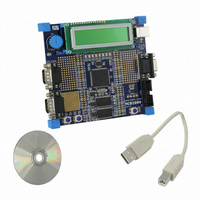
BOARD EVAL FOR LPC2919
Manufacturer
NXP Semiconductors
Series
Keilr
Type
MCUr
Datasheet
1.OM11014.pdf
(67 pages)
Specifications of OM11014
Contents
Board, Cable, CD
For Use With/related Products
LPC2919
Lead Free Status / RoHS Status
Not applicable / Not applicable
Other names
568-4360


NXP Semiconductors
2.
LPC2917_19_1
Product data sheet
Fig 14. PLL block diagram
Generation of the main clock is restricted by the frequency range of the PLL clock input. See
input clock
8.8.4.3 PLL functional description
appropriate ‘CLK_SEL’ values are masked and unmasked accordingly. Each clock
detector can also generate interrupts at clock activation and deactivation so that the
system can be notified of a change in internal clock status.
Clock detection is done using a counter running at the BASE_PCR_CLK frequency. If no
positive clock edge occurs before the counter has 32 cycles of BASE_PCR_CLK the clock
is assumed to be inactive. As BASE_PCR_CLK is slower than any of the clocks to be
detected, normally only one BASE_PCR_CLK cycle is needed to detect activity. After
reset all clocks are assumed to be ‘non-present’, so the RDET status register will be
correct only after 32 BASE_PCR_CLK cycles.
Note that this mechanism cannot protect against a currently-selected clock going from
active to inactive state. Therefore an inactive clock may still be sent to the system under
special circumstances, although an interrupt can still be generated to notify the system.
Glitch-Free Switching:
glitch-free, both at the output generator stage and also at secondary source generators.
In the case of the PLL the clock will be stopped and held low for long enough to allow the
PLL to stabilize and lock before being re-enabled. For all non-PLL Generators the switch
will occur as quickly as possible, although there will always be a period when the clock is
held low due to synchronization requirements.
If the current clock is high and does not go low within 32 cycles of BASE_PCR_CLK it is
assumed to be inactive and is asynchronously forced low. This prevents deadlocks on the
interface.
A block diagram of the PLL is shown in
analog section. This block compares the phase and frequency of the inputs and generates
the main clock
to create the output clock, or sent directly to the output. The main output clock is then
divided by M by the programmable feedback divider to generate the feedback clock. The
output signal of the analog section is also monitored by the lock detector to signal when
the PLL has locked onto the input clock.
CCO
2
. These clocks are either divided by 2*P by the programmable post divider
bypass
Rev. 01 — 31 July 2008
Provisions are included in the CGU to allow clocks to be switched
MSEL bits
PSEL bits
/ 2PDIV
/ MDIV
Figure
ARM9 microcontroller with CAN and LIN
14. The input clock is fed directly to the
direct
Table
clkout
P23EN bit
31, Dynamic characteristics.
P23
LPC2917/19
© NXP B.V. 2008. All rights reserved.
clkout120
clkout240
clkout
002aad833
44 of 67
Related parts for OM11014
Image
Part Number
Description
Manufacturer
Datasheet
Request
R

Part Number:
Description:
NXP Semiconductors designed the LPC2420/2460 microcontroller around a 16-bit/32-bitARM7TDMI-S CPU core with real-time debug interfaces that include both JTAG andembedded trace
Manufacturer:
NXP Semiconductors
Datasheet:

Part Number:
Description:
NXP Semiconductors designed the LPC2458 microcontroller around a 16-bit/32-bitARM7TDMI-S CPU core with real-time debug interfaces that include both JTAG andembedded trace
Manufacturer:
NXP Semiconductors
Datasheet:
Part Number:
Description:
NXP Semiconductors designed the LPC2468 microcontroller around a 16-bit/32-bitARM7TDMI-S CPU core with real-time debug interfaces that include both JTAG andembedded trace
Manufacturer:
NXP Semiconductors
Datasheet:
Part Number:
Description:
NXP Semiconductors designed the LPC2470 microcontroller, powered by theARM7TDMI-S core, to be a highly integrated microcontroller for a wide range ofapplications that require advanced communications and high quality graphic displays
Manufacturer:
NXP Semiconductors
Datasheet:
Part Number:
Description:
NXP Semiconductors designed the LPC2478 microcontroller, powered by theARM7TDMI-S core, to be a highly integrated microcontroller for a wide range ofapplications that require advanced communications and high quality graphic displays
Manufacturer:
NXP Semiconductors
Datasheet:
Part Number:
Description:
The Philips Semiconductors XA (eXtended Architecture) family of 16-bit single-chip microcontrollers is powerful enough to easily handle the requirements of high performance embedded applications, yet inexpensive enough to compete in the market for hi
Manufacturer:
NXP Semiconductors
Datasheet:
Part Number:
Description:
The XA-S3 device is a member of Philips Semiconductors? XA(eXtended Architecture) family of high performance 16-bitsingle-chip microcontrollers
Manufacturer:
NXP Semiconductors
Datasheet:

Part Number:
Description:
The NXP BlueStreak LH75401/LH75411 family consists of two low-cost 16/32-bit System-on-Chip (SoC) devices
Manufacturer:
NXP Semiconductors
Datasheet:
Part Number:
Description:
The NXP LPC3130/3131 combine an 180 MHz ARM926EJ-S CPU core, high-speed USB2
Manufacturer:
NXP Semiconductors
Datasheet:
Part Number:
Description:
The NXP LPC3141 combine a 270 MHz ARM926EJ-S CPU core, High-speed USB 2
Manufacturer:
NXP Semiconductors
Part Number:
Description:
The NXP LPC3143 combine a 270 MHz ARM926EJ-S CPU core, High-speed USB 2
Manufacturer:
NXP Semiconductors

Part Number:
Description:
The NXP LPC3152 combines an 180 MHz ARM926EJ-S CPU core, High-speed USB 2
Manufacturer:
NXP Semiconductors
Part Number:
Description:
The NXP LPC3154 combines an 180 MHz ARM926EJ-S CPU core, High-speed USB 2
Manufacturer:
NXP Semiconductors

Part Number:
Description:
Standard level N-channel enhancement mode Field-Effect Transistor (FET) in a plastic package using NXP High-Performance Automotive (HPA) TrenchMOS technology
Manufacturer:
NXP Semiconductors
Datasheet: