TOOLSTICK540DC Silicon Laboratories Inc, TOOLSTICK540DC Datasheet - Page 141
TOOLSTICK540DC
Manufacturer Part Number
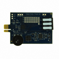
TOOLSTICK540DC
Description
DAUGHTER CARD TOOLSTICK F540
Manufacturer
Silicon Laboratories Inc
Series
ToolStickr
Type
MCUr
Datasheets
1.TOOLSTICK540DC.pdf
(274 pages)
2.TOOLSTICK540DC.pdf
(16 pages)
3.TOOLSTICK540DC.pdf
(12 pages)
Specifications of TOOLSTICK540DC
Contents
Daughter Card
Processor To Be Evaluated
C8051F54x
Processor Series
C8051F54x
Interface Type
USB
Operating Supply Voltage
2.7 V to 3.6 V
Lead Free Status / RoHS Status
Lead free / RoHS Compliant
For Use With/related Products
C8051F54x
For Use With
336-1345 - TOOLSTICK BASE ADAPTER336-1182 - ADAPTER USB DEBUG FOR C8051FXXX
Lead Free Status / Rohs Status
Lead free / RoHS Compliant
Other names
336-1717


SFR Definition 17.5. CLKMUL: Clock Multiplier
SFR Address = 0x97; SFR Page = 0x0F;
Notes: The maximum system clock is 50 MHz, and so the Clock Multiplier output should be scaled accordingly.
Name
Reset
Bit
4:2
1:0
Type
7
6
5
Bit
MULSEL[1:0] Clock Multiplier Input Select.
If Internal Oscillator x 2 or External Oscillator x 2 is selected using the MULSEL bits, MULDIV[2:0] is ignored.
MULDIV[2:0]
MULRDY
MULINIT
MULEN
MULEN
Name
R/W
7
0
MULINIT
Clock Multiplier Enable.
0: Clock Multiplier disabled.
1: Clock Multiplier enabled.
Clock Multiplier Initialize.
This bit is 0 when the Clock Multiplier is enabled. Once enabled, writing a 1 to this
bit will initialize the Clock Multiplier. The MULRDY bit reads 1 when the Clock Mul-
tiplier is stabilized.
Clock Multiplier Ready.
0: Clock Multiplier is not ready.
1: Clock Multiplier is ready (PLL is locked).
Clock Multiplier Output Scaling Factor.
000: Clock Multiplier Output scaled by a factor of 1.
001: Clock Multiplier Output scaled by a factor of 1.
010: Clock Multiplier Output scaled by a factor of 1.
011: Clock Multiplier Output scaled by a factor of 2/3*.
100: Clock Multiplier Output scaled by a factor of 2/4 (1/2).
101: Clock Multiplier Output scaled by a factor of 2/5*.
110: Clock Multiplier Output scaled by a factor of 2/6 (1/3).
111: Clock Multiplier Output scaled by a factor of 2/7*.
*Note: The Clock Multiplier output duty cycle is not 50% for these settings.
These bits select the clock supplied to the Clock Multiplier
MULSEL[1:0]
R/W
6
0
00
01
10
11
MULRDY
R
5
0
Selected Input Clock
External Oscillator
External Oscillator
Internal Oscillator
Internal Oscillator
Rev. 1.1
4
0
MULDIV[2:0]
Function
R/W
3
0
2
0
Clock Multiplier Output
for MULDIV[2:0] = 000b
External Oscillator x 2
External Oscillator x 4
Internal Oscillator x 2
Internal Oscillator x 4
C8051F54x
1
MULSEL[1:0]
0
R/W
0
0
141
Related parts for TOOLSTICK540DC
Image
Part Number
Description
Manufacturer
Datasheet
Request
R

Part Number:
Description:
KIT TOOL EVAL SYS IN A USB STICK
Manufacturer:
Silicon Laboratories Inc
Datasheet:

Part Number:
Description:
TOOLSTICK DEBUG ADAPTER
Manufacturer:
Silicon Laboratories Inc
Datasheet:

Part Number:
Description:
TOOLSTICK BASE ADAPTER
Manufacturer:
Silicon Laboratories Inc
Datasheet:

Part Number:
Description:
TOOLSTICK DAUGHTER CARD
Manufacturer:
Silicon Laboratories Inc
Datasheet:

Part Number:
Description:
TOOLSTICK DAUGHTER CARD
Manufacturer:
Silicon Laboratories Inc
Datasheet:

Part Number:
Description:
TOOLSTICK DAUGHTER CARD
Manufacturer:
Silicon Laboratories Inc
Datasheet:

Part Number:
Description:
TOOLSTICK PROGRAMMING ADAPTER
Manufacturer:
Silicon Laboratories Inc
Datasheet:

Part Number:
Description:
TOOLSTICK DAUGHTER CARD
Manufacturer:
Silicon Laboratories Inc
Datasheet:

Part Number:
Description:
KIT STARTER TOOLSTICK
Manufacturer:
Silicon Laboratories Inc
Datasheet:

Part Number:
Description:
KIT UNIVERSITY TOOLSTICK STARTER
Manufacturer:
Silicon Laboratories Inc
Datasheet:

Part Number:
Description:
DAUGHTER CARD TOOLSTICK F330
Manufacturer:
Silicon Laboratories Inc
Datasheet:

Part Number:
Description:
CARD DAUGHTER UNIVRSTY TOOLSTICK
Manufacturer:
Silicon Laboratories Inc
Datasheet:

Part Number:
Description:
DAUGHTER CARD TOOLSTICK F582
Manufacturer:
Silicon Laboratories Inc
Datasheet:

Part Number:
Description:
DAUGHTER CARD TOOLSTICK F500
Manufacturer:
Silicon Laboratories Inc
Datasheet:

Part Number:
Description:
DAUGHTER CARD TOOLSTICK F560
Manufacturer:
Silicon Laboratories Inc
Datasheet: