TOOLSTICK540DC Silicon Laboratories Inc, TOOLSTICK540DC Datasheet - Page 227
TOOLSTICK540DC
Manufacturer Part Number
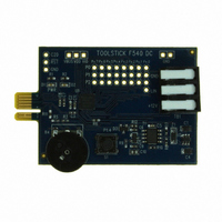
TOOLSTICK540DC
Description
DAUGHTER CARD TOOLSTICK F540
Manufacturer
Silicon Laboratories Inc
Series
ToolStickr
Type
MCUr
Datasheets
1.TOOLSTICK540DC.pdf
(274 pages)
2.TOOLSTICK540DC.pdf
(16 pages)
3.TOOLSTICK540DC.pdf
(12 pages)
Specifications of TOOLSTICK540DC
Contents
Daughter Card
Processor To Be Evaluated
C8051F54x
Processor Series
C8051F54x
Interface Type
USB
Operating Supply Voltage
2.7 V to 3.6 V
Lead Free Status / RoHS Status
Lead free / RoHS Compliant
For Use With/related Products
C8051F54x
For Use With
336-1345 - TOOLSTICK BASE ADAPTER336-1182 - ADAPTER USB DEBUG FOR C8051FXXX
Lead Free Status / Rohs Status
Lead free / RoHS Compliant
Other names
336-1717


23. Timers
Each MCU includes four counter/timers: two are 16-bit counter/timers compatible with those found in the
standard 8051, and two are 16-bit auto-reload timer for use with the ADC, SMBus, or for general purpose
use. These timers can be used to measure time intervals, count external events and generate periodic
interrupt requests. Timer 0 and Timer 1 are nearly identical and have four primary modes of operation.
Timer 2 and Timer 3 offer 16-bit and split 8-bit timer functionality with auto-reload.
Timers 0 and 1 may be clocked by one of five sources, determined by the Timer Mode Select bits (T1M –
T0M) and the Clock Scale bits (SCA1 – SCA0). The Clock Scale bits define a pre-scaled clock from which
Timer 0 and/or Timer 1 may be clocked (See SFR Definition 23.1 for pre-scaled clock selection).Timer 0/1
may then be configured to use this pre-scaled clock signal or the system clock.
Timer 2 and Timer 3 may be clocked by the system clock, the system clock divided by 12, or the external
oscillator clock source divided by 8.
Timer 0 and Timer 1 may also be operated as counters. When functioning as a counter, a counter/timer
register is incremented on each high-to-low transition at the selected input pin (T0 or T1). Events with a fre-
quency of up to one-fourth the system clock frequency can be counted. The input signal need not be peri-
odic, but it should be held at a given level for at least two full system clock cycles to ensure the level is
properly sampled.
13-bit counter/timer
16-bit counter/timer
8-bit counter/timer with
auto-reload
Two 8-bit counter/timers (Timer 0
only)
Timer 0 and Timer 1 Modes
16-bit timer with auto-reload
Two 8-bit timers with auto-reload
Timer 2 Modes
Rev. 1.1
16-bit timer with auto-reload
Two 8-bit timers with auto-reload
Timer 3 Modes
C8051F54x
227
Related parts for TOOLSTICK540DC
Image
Part Number
Description
Manufacturer
Datasheet
Request
R

Part Number:
Description:
KIT TOOL EVAL SYS IN A USB STICK
Manufacturer:
Silicon Laboratories Inc
Datasheet:

Part Number:
Description:
TOOLSTICK DEBUG ADAPTER
Manufacturer:
Silicon Laboratories Inc
Datasheet:

Part Number:
Description:
TOOLSTICK BASE ADAPTER
Manufacturer:
Silicon Laboratories Inc
Datasheet:

Part Number:
Description:
TOOLSTICK DAUGHTER CARD
Manufacturer:
Silicon Laboratories Inc
Datasheet:

Part Number:
Description:
TOOLSTICK DAUGHTER CARD
Manufacturer:
Silicon Laboratories Inc
Datasheet:

Part Number:
Description:
TOOLSTICK DAUGHTER CARD
Manufacturer:
Silicon Laboratories Inc
Datasheet:

Part Number:
Description:
TOOLSTICK PROGRAMMING ADAPTER
Manufacturer:
Silicon Laboratories Inc
Datasheet:

Part Number:
Description:
TOOLSTICK DAUGHTER CARD
Manufacturer:
Silicon Laboratories Inc
Datasheet:

Part Number:
Description:
KIT STARTER TOOLSTICK
Manufacturer:
Silicon Laboratories Inc
Datasheet:

Part Number:
Description:
KIT UNIVERSITY TOOLSTICK STARTER
Manufacturer:
Silicon Laboratories Inc
Datasheet:

Part Number:
Description:
DAUGHTER CARD TOOLSTICK F330
Manufacturer:
Silicon Laboratories Inc
Datasheet:

Part Number:
Description:
CARD DAUGHTER UNIVRSTY TOOLSTICK
Manufacturer:
Silicon Laboratories Inc
Datasheet:

Part Number:
Description:
DAUGHTER CARD TOOLSTICK F582
Manufacturer:
Silicon Laboratories Inc
Datasheet:

Part Number:
Description:
DAUGHTER CARD TOOLSTICK F500
Manufacturer:
Silicon Laboratories Inc
Datasheet:

Part Number:
Description:
DAUGHTER CARD TOOLSTICK F560
Manufacturer:
Silicon Laboratories Inc
Datasheet: