TOOLSTICK540DC Silicon Laboratories Inc, TOOLSTICK540DC Datasheet - Page 233
TOOLSTICK540DC
Manufacturer Part Number
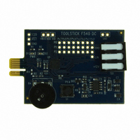
TOOLSTICK540DC
Description
DAUGHTER CARD TOOLSTICK F540
Manufacturer
Silicon Laboratories Inc
Series
ToolStickr
Type
MCUr
Datasheets
1.TOOLSTICK540DC.pdf
(274 pages)
2.TOOLSTICK540DC.pdf
(16 pages)
3.TOOLSTICK540DC.pdf
(12 pages)
Specifications of TOOLSTICK540DC
Contents
Daughter Card
Processor To Be Evaluated
C8051F54x
Processor Series
C8051F54x
Interface Type
USB
Operating Supply Voltage
2.7 V to 3.6 V
Lead Free Status / RoHS Status
Lead free / RoHS Compliant
For Use With/related Products
C8051F54x
For Use With
336-1345 - TOOLSTICK BASE ADAPTER336-1182 - ADAPTER USB DEBUG FOR C8051FXXX
Lead Free Status / Rohs Status
Lead free / RoHS Compliant
Other names
336-1717


SFR Definition 23.2. TCON: Timer Control
SFR Address = 0x88; Bit-Addressable; SFR Page = All Pages
Name
Reset
Bit
Type
7
6
5
4
3
2
1
0
Bit
Name
TR1
TR0
TF1
TF0
IE1
IE0
IT1
IT0
R/W
TF1
7
0
Timer 1 Overflow Flag.
Set to 1 by hardware when Timer 1 overflows. This flag can be cleared by software
but is automatically cleared when the CPU vectors to the Timer 1 interrupt service
routine.
Timer 1 Run Control.
Timer 1 is enabled by setting this bit to 1.
Timer 0 Overflow Flag.
Set to 1 by hardware when Timer 0 overflows. This flag can be cleared by software
but is automatically cleared when the CPU vectors to the Timer 0 interrupt service
routine.
Timer 0 Run Control.
Timer 0 is enabled by setting this bit to 1.
External Interrupt 1.
This flag is set by hardware when an edge/level of type defined by IT1 is detected. It
can be cleared by software but is automatically cleared when the CPU vectors to the
External Interrupt 1 service routine in edge-triggered mode.
Interrupt 1 Type Select.
This bit selects whether the configured INT1 interrupt will be edge or level sensitive.
INT1 is configured active low or high by the IN1PL bit in the IT01CF register (see
SFR Definition 13.7).
0: INT1 is level triggered.
1: INT1 is edge triggered.
External Interrupt 0.
This flag is set by hardware when an edge/level of type defined by IT1 is detected. It
can be cleared by software but is automatically cleared when the CPU vectors to the
External Interrupt 0 service routine in edge-triggered mode.
Interrupt 0 Type Select.
This bit selects whether the configured INT0 interrupt will be edge or level sensitive.
INT0 is configured active low or high by the IN0PL bit in register IT01CF (see SFR
Definition 13.7).
0: INT0 is level triggered.
1: INT0 is edge triggered.
R/W
TR1
6
0
R/W
TF0
5
0
TR0
R/W
Rev. 1.1
4
0
Function
R/W
IE1
3
0
R/W
IT1
2
0
C8051F54x
R/W
IE0
1
0
R/W
IT0
0
0
233
Related parts for TOOLSTICK540DC
Image
Part Number
Description
Manufacturer
Datasheet
Request
R

Part Number:
Description:
KIT TOOL EVAL SYS IN A USB STICK
Manufacturer:
Silicon Laboratories Inc
Datasheet:

Part Number:
Description:
TOOLSTICK DEBUG ADAPTER
Manufacturer:
Silicon Laboratories Inc
Datasheet:

Part Number:
Description:
TOOLSTICK BASE ADAPTER
Manufacturer:
Silicon Laboratories Inc
Datasheet:

Part Number:
Description:
TOOLSTICK DAUGHTER CARD
Manufacturer:
Silicon Laboratories Inc
Datasheet:

Part Number:
Description:
TOOLSTICK DAUGHTER CARD
Manufacturer:
Silicon Laboratories Inc
Datasheet:

Part Number:
Description:
TOOLSTICK DAUGHTER CARD
Manufacturer:
Silicon Laboratories Inc
Datasheet:

Part Number:
Description:
TOOLSTICK PROGRAMMING ADAPTER
Manufacturer:
Silicon Laboratories Inc
Datasheet:

Part Number:
Description:
TOOLSTICK DAUGHTER CARD
Manufacturer:
Silicon Laboratories Inc
Datasheet:

Part Number:
Description:
KIT STARTER TOOLSTICK
Manufacturer:
Silicon Laboratories Inc
Datasheet:

Part Number:
Description:
KIT UNIVERSITY TOOLSTICK STARTER
Manufacturer:
Silicon Laboratories Inc
Datasheet:

Part Number:
Description:
DAUGHTER CARD TOOLSTICK F330
Manufacturer:
Silicon Laboratories Inc
Datasheet:

Part Number:
Description:
CARD DAUGHTER UNIVRSTY TOOLSTICK
Manufacturer:
Silicon Laboratories Inc
Datasheet:

Part Number:
Description:
DAUGHTER CARD TOOLSTICK F582
Manufacturer:
Silicon Laboratories Inc
Datasheet:

Part Number:
Description:
DAUGHTER CARD TOOLSTICK F500
Manufacturer:
Silicon Laboratories Inc
Datasheet:

Part Number:
Description:
DAUGHTER CARD TOOLSTICK F560
Manufacturer:
Silicon Laboratories Inc
Datasheet: