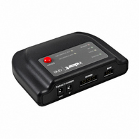
INDART-ONE/FSL SofTec Microsystems SRL, INDART-ONE/FSL Datasheet - Page 61

INDART-ONE/FSL
Manufacturer Part Number
INDART-ONE/FSL
Description
PROG/DEBUG FOR HC08/HCS08/HCS12
Manufacturer
SofTec Microsystems SRL
Series
inDARTr
Type
In-Circuit, Real-Time Debugger/Programmerr
Datasheets
1.INDART-ONEFSL.pdf
(2 pages)
2.INDART-ONEFSL.pdf
(140 pages)
3.INDART-ONEFSL.pdf
(2 pages)
Specifications of INDART-ONE/FSL
Contents
In-circuit debugger/programmer unit, Cables, Evaluation Board and Software
For Use With/related Products
Freescale HC08/S08/RS08/S12/S12X
Lead Free Status / RoHS Status
Lead free / RoHS Compliant
Other names
520-1038
INDART-ONE
INDART-ONE
- Current page: 61 of 140
- Download datasheet (2Mb)
The “TARGET POWER Connectors” parameter specifies how the two
“TARGET POWER” connectors work.
When the first option (“Mode A”) is selected, the user-supplied voltage at the
“TARGET POWER IN” connector is routed to the target board via the
“TARGET POWER OUT” connector, through an internal relay driven by
inDART-One.
When the second option (“Mode B”) is selected, the voltage at the “TARGET
POWER OUT” connector is internally generated by inDART-One, and the
“TARGET POWER IN” connector is not used. The generated voltage is as
specified by the “Target Voltage Selection” parameter.
“Power down time”. The time it takes for the power voltage to drop
below 100 mV.
“Power up time”. The time it takes for target microcontroller to get
ready to communicate after the V
i
Figure 5.3: MON08 Communication Settings: Target Power Connectors Modes
Note: when “Mode B” is selected, only the central pin of the
“TARGET POWER OUT” connector is used, while the outer
sleeve is not connected. The GND reference is taken from
the “MON08” cable.
DD
voltage becomes high.
inDART-One User's Manual
59
5
Related parts for INDART-ONE/FSL
Image
Part Number
Description
Manufacturer
Datasheet
Request
R

Part Number:
Description:
KIT DEBUGGER IN-CIRC ST7 FLASH
Manufacturer:
STMicroelectronics
Datasheet:

Part Number:
Description:
KIT DEBUGGER IN-CIRC ST7 USB
Manufacturer:
STMicroelectronics
Datasheet:

Part Number:
Description:
KIT STARTER FOR ST7
Manufacturer:
SofTec Microsystems SRL
Datasheet:

Part Number:
Description:
KIT DESIGN FOR ST7
Manufacturer:
SofTec Microsystems SRL
Datasheet:

Part Number:
Description:
KIT DESIGN USB FOR HCO8
Manufacturer:
SofTec Microsystems SRL
Datasheet:

Part Number:
Description:
KIT DESIGN USB FOR HCO8
Manufacturer:
SofTec Microsystems SRL
Datasheet:

Part Number:
Description:
KIT DESIGN USB FOR HCO8
Manufacturer:
SofTec Microsystems SRL
Datasheet:

Part Number:
Description:
KIT DESIGN USB FOR HCO8
Manufacturer:
SofTec Microsystems SRL
Datasheet:

Part Number:
Description:
KIT DESIGN USB FOR HCS12
Manufacturer:
SofTec Microsystems SRL
Datasheet:

Part Number:
Description:
KIT DESIGN USB FOR HCS12
Manufacturer:
SofTec Microsystems SRL
Datasheet:

Part Number:
Description:
KIT DESIGN USB FOR HCS12
Manufacturer:
SofTec Microsystems SRL
Datasheet:

Part Number:
Description:
KIT DESIGN USB FOR HCO8
Manufacturer:
SofTec Microsystems SRL
Datasheet:

Part Number:
Description:
KIT DESIGN USB FOR HCO8
Manufacturer:
SofTec Microsystems SRL
Datasheet:

Part Number:
Description:
KIT DESIGN USB FOR HCO8
Manufacturer:
SofTec Microsystems SRL
Datasheet:

Part Number:
Description:
KIT DESIGN USB FOR HCSO8
Manufacturer:
SofTec Microsystems SRL
Datasheet:


