STEVAL-IFS001V1 STMicroelectronics, STEVAL-IFS001V1 Datasheet - Page 13
STEVAL-IFS001V1
Manufacturer Part Number
STEVAL-IFS001V1
Description
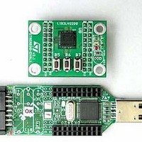
EVAL BOARD 3AXIS MEMS ACCELLRMTR
Manufacturer
STMicroelectronics
Series
MEMSr
Datasheets
1.STEVAL-IFS001V1.pdf
(42 pages)
2.STEVAL-IFS001V1.pdf
(14 pages)
3.STEVAL-IFS001V1.pdf
(4 pages)
4.STEVAL-IFS001V1.pdf
(14 pages)
Specifications of STEVAL-IFS001V1
Design Resources
STEVAL-IFS001V1 Gerber Files STEVAL-IFS001V1 Schematic STEVAL-IFS001V1 Bill of Material
Sensor Type
Accelerometer, 3 Axis
Sensing Range
±2g, 6g
Interface
I²C, SPI
Sensitivity
1024 LSb/g
Voltage - Supply
2.16 V ~ 3.6 V
Embedded
Yes, MCU, 8-Bit
Utilized Ic / Part
LIS3LV02DQ
Processor To Be Evaluated
LIS3LV02DQ
Interface Type
USB
Lead Free Status / RoHS Status
Contains lead / RoHS non-compliant
Other names
497-5069
Available stocks
Company
Part Number
Manufacturer
Quantity
Price


LIS3LV02DQ
2.4
2.4.1
2.4.2
2.4.3
Terminology
Sensitivity
Sensitivity describes the gain of the sensor and can be determined e.g. by applying 1g
acceleration to it. As the sensor can measure DC accelerations this can be done easily by
pointing the axis of interest towards the center of the earth, noting the output value, rotating the
sensor by 180 degrees (point to the sky) and noting the output value again. By doing so, ±1g
acceleration is applied to the sensor. Subtracting the larger output value from the smaller one
and divide the result by 2 leads to the actual sensitivity of the sensor. This value changes very
little over temperature and also very little over time. The Sensitivity Tolerance describes the
range of Sensitivities of a large population of sensor.
Zero-g level
Zero-g level Offset (Off) describes the deviation of an actual output signal from the ideal output
signal if there is no acceleration present. A sensor in a steady state on a horizontal surface will
measure 0g in X axis and 0g in Y axis whereas the Z axis will measure 1g. The output is ideally
in the middle of the dynamic range of the sensor (content of OUT registers 00h, 00h with 16 bit
representation, data expressed as 2’s complement number). A deviation from ideal value in this
case is called Zero-g offset. Offset is to some extent a result of stress to a precise MEMS
sensor and therefore the offset can slightly change after mounting the sensor onto a printed
circuit board or exposing it to extensive mechanical stress. Offset changes little over
temperature, see “Zero-g level change vs. temperature”. The Zero-g level of an individual
sensor is stable over lifetime. The Zero-g level tolerance describes the range of Zero-g levels of
a population of sensors.
Self Test
Self Test allows to test the mechanical and electric part of the sensor, allowing the seismic
mass to be moved by means of an electrostatic test-force. The Self Test function is off when the
self-test bit of ctrl_reg1 (control register 1) is programmed to ‘0‘. When the self-test bit of
ctrl_reg1 is programmed to ‘1‘ an actuation force is applied to the sensor, simulating a definite
input acceleration. In this case the sensor outputs will exhibit a change in their DC levels which
is related to the selected full scale and depending on the Supply Voltage through the device
sensitivity. When Self Test is activated, the device output level is given by the algebraic sum of
the signals produced by the acceleration acting on the sensor and by the electrostatic test-
force. If the output signals change within the amplitude specified inside table 2 or table 3, than
the sensor is working properly and the parameters of the interface chip are within the defined
specification.
CD00047926
2 Mechanical and Electrical specifications
13/42
Related parts for STEVAL-IFS001V1
Image
Part Number
Description
Manufacturer
Datasheet
Request
R

Part Number:
Description:
BOARD EVAL SPZB260 MOD FOR STR9
Manufacturer:
STMicroelectronics
Datasheet:

Part Number:
Description:
BOARD EVAL EXTENSION SN250
Manufacturer:
STMicroelectronics
Datasheet:

Part Number:
Description:
BOARD EVAL AB-54003L-512
Manufacturer:
STMicroelectronics
Datasheet:

Part Number:
Description:
BOARD REF DESIGN RF DMOS PWR AMP
Manufacturer:
STMicroelectronics
Datasheet:

Part Number:
Description:
BOARD EVAL PWR AMP AB-84008L-470
Manufacturer:
STMicroelectronics
Datasheet:

Part Number:
Description:
BOARD EVAL FOR STM32F103XX
Manufacturer:
STMicroelectronics
Datasheet:

Part Number:
Description:
BOARD EVAL AB-54003L-512
Manufacturer:
STMicroelectronics
Datasheet:

Part Number:
Description:
BOARD SMART PLUG STM32 SPZB260PR
Manufacturer:
STMicroelectronics
Datasheet:

Part Number:
Description:
BOARD DEMO BLUETOOTH SPBT2532C2
Manufacturer:
STMicroelectronics
Datasheet:
Part Number:
Description:
ZIGBEE USB DONGLE EVAL KIT
Manufacturer:
STMicroelectronics
Datasheet:
Part Number:
Description:
STMicroelectronics [RIPPLE-CARRY BINARY COUNTER/DIVIDERS]
Manufacturer:
STMicroelectronics
Datasheet:
Part Number:
Description:
STMicroelectronics [LIQUID-CRYSTAL DISPLAY DRIVERS]
Manufacturer:
STMicroelectronics
Datasheet:

Part Number:
Description:
BOARD EVAL FOR MEMS SENSORS
Manufacturer:
STMicroelectronics
Datasheet: